
Page 475 - The Mechatronics Handbook
P. 475
0066_frame_C19 Page 97 Wednesday, January 9, 2002 5:32 PM
Transmitted
Transmitter TTL sinc
Function Frequency Volts
Generator Divider
Phase
Phase 2
Received Detection
Receiver TTL wave
Frequency
to TTL Divider
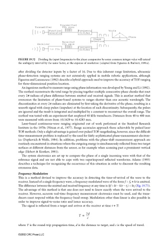
FIGURE 19.72 Dividing the input frequencies to the phase comparator by some common integer value will extend
the ambiguity interval by the same factor, at the expense of resolution (adapted from Figueroa & Barbieri, 1991a).
after dividing the detector inputs by a factor of 16. Due to this inherent range limitation, ultrasonic
phase-detection ranging systems are not extensively applied in mobile robotic applications, although
Figueroa and Lamancusa (1992) describe a hybrid approach used to improve the accuracy of TOF ranging
for three-dimensional position location.
An ingenious method to measure range using phase information was developed by Young and Li (1992).
The method reconstructs the total range by piecing together multiple consecutive phase chunks that reset
every 2π radians of phase difference between emitted and received signals. This is another method that
overcomes the limitation of phase-based systems to ranges shorter than one acoustic wavelength. The
discontinuities at every 2π radians are eliminated by first taking the derivative of the phase, resulting in a
smooth signal with sharp pulses (impulses) at the location of each discontinuity. Subsequently, the pulses
are ignored and the result is integrated and multiplied by a constant to reconstruct the overall range. The
method was tested with an experiment that employed 40 kHz transducers. Distances from 40 to 400 mm
were measured with errors from ±0.1629 to ±0.4283 mm.
Laser-based continuous-wave ranging originated out of work performed at the Stanford Research
Institute in the 1970s (Nitzan et al., 1977). Range accuracies approach those achievable by pulsed laser
TOF methods. Only a slight advantage is gained over pulsed TOF rangefinding, however, since the difficult
time-measurement problem is replaced by the need for fairly sophisticated phase-measurement electron-
ics (Depkovich & Wolfe, 1984). In addition, problems with the phase-shift measurement approach are
routinely encountered in situations where the outgoing energy is simultaneously reflected from two target
surfaces at different distances from the sensor, as for example when scanning past a prominent vertical
edge (Hebert & Krotkov, 1991).
The system electronics are set up to compare the phase of a single incoming wave with that of the
reference signal and are not able to cope with two superimposed reflected waveforms. Adams (1993)
describes a technique for recognizing the occurrence of this situation in order to discount the resulting
erroneous data.
Frequency Modulation
This is a method devised to improve the accuracy in detecting the time-of-arrival of the wave to the
receiver. Instead of a single frequency wave, a frequency modulated wave of the form f = f 0 + kt is emitted.
The difference between the emitted and received frequency at any time is ∆f = kt − k(t − t f ) = kt f (Fig. 19.73).
The advantage of this method is that one does not need to know exactly when the wave arrived to the
receiver. However, accurate real-time frequency measurement electronics must be used, and the trans-
ducers must respond within the frequency band sweep. Modulation other than linear is also possible in
order to improve signal-to-noise ratio and hence accuracy.
The signal is reflected from a target and arrives at the receiver at time t + T:
T = 2d
------
c
where T is the round-trip propagation time, d is the distance to target, and c is the speed of travel.
©2002 CRC Press LLC