
Page 482 - The Mechatronics Handbook
P. 482
0066_frame_C19 Page 104 Wednesday, January 9, 2002 5:32 PM
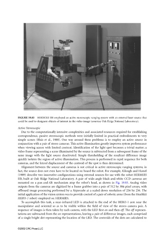
FIGURE 19.83 HERMIES IIB employed an active stereoscopic ranging system with an external laser source that
could be used to designate objects of interest in the video image (courtesy Oak Ridge National Laboratory).
Active Stereoscopic
Due to the computationally intensive complexities and associated resources required for establishing
correspondence, passive stereoscopic methods were initially limited in practical embodiments to very
simple scenes (Blais et al., 1988). One way around these problems is to employ an active source in
conjunction with a pair of stereo cameras. This active illumination greatly improves system performance
when viewing scenes with limited contrast. Identification of the light spot becomes a trivial matter; a
video frame representing a scene illuminated by the source is subtracted from a subsequent frame of the
same image with the light source deactivated. Simple thresholding of the resultant difference image
quickly isolates the region of active illumination. This process is performed in rapid sequence for both
cameras, and the lateral displacement of the centroid of the spot is then determined.
Alignment between the source and cameras is not critical in active stereoscopic ranging systems; in
fact, the source does not even have to be located on board the robot. For example, Kilough and Hamel
(1989) describe two innovative configurations using external sources for use with the robot HERMIES
IIB, built at Oak Ridge National Laboratory. A pair of wide-angle black-and-white CCD cameras are
mounted on a pan-and-tilt mechanism atop the robot’s head, as shown in Fig. 19.83. Analog video
outputs from the cameras are digitized by a frame grabber into a pair of 512 by 384-pixel arrays, with
offboard image processing performed by a Hypercube at a scaled-down resolution of 256 by 256. The
initial application of the vision system was to provide control of a pair of robotic arms (from the Heathkit
HERO-1 robot) employed on HERMIES.
To accomplish this task, a near-infrared LED is attached to the end of the HERO-1 arm near the
manipulator and oriented so as to be visible within the field of view of the stereo camera pair. A
sequence of images is then taken by each camera, with the LED first on and then off. The off represen-
tations are subtracted from the on representations, leaving a pair of difference images, each comprised
of a single bright dot representing the location of the LED. The centroids of the dots are calculated to
©2002 CRC Press LLC