
Page 486 - The Mechatronics Handbook
P. 486
0066_frame_C19 Page 108 Wednesday, January 9, 2002 5:32 PM
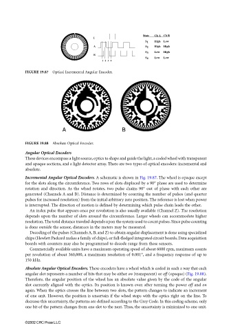
I State Ch A Ch B
S 1 High Low
A S 2 High High
S 3 Low High
B
S 4 Low Low
12 3 4
FIGURE 19.87 Optical Incremental Angular Encoder.
A B
FIGURE 19.88 Absolute Optical Encoder.
Angular Optical Encoders
These devices encompass a light source, optics to shape and guide the light, a coded wheel with transparent
and opaque sections, and a light detector array. There are two types of optical encoders: incremental and
absolute.
Incremental Angular Optical Encoders. A schematic is shown in Fig. 19.87. The wheel is opaque except
for the slots along the circumference. Two rows of slots displaced by a 90° phase are used to determine
rotation and direction. As the wheel rotates, two pulse chains 90° out of phase with each other are
generated (Channels A and B). Distance is determined by counting the number of pulses (and quarter
pulses for increased resolution) from the initial arbitrary zero position. The reference is lost when power
is interrupted. The direction of motion is defined by determining which pulse chain leads the other.
An index pulse that appears once per revolution is also usually available (Channel Z). The resolution
depends upon the number of slots around the circumference. Larger wheels can accommodate higher
resolution. The total distance traveled depends upon the system used to count pulses. Since pulse counting
is done outside the sensor, distances in the meters may be measured.
Decoding of the pulses (Channels A, B, and Z) to obtain angular displacement is done using specialized
chips (Hewlett Packard makes a family of chips), or full-fledged integrated circuit boards. Data acquisition
boards with counters may also be programmed to decode range from these sensors.
Commercially available units have a maximum operating speed of about 6000 rpm, maximum counts
per revolution of about 360,000, a maximum resolution of 0.001°, and a frequency response of up to
150 kHz.
Absolute Angular Optical Encoders. These encoders have a wheel which is coded in such a way that each
angular slot represents a number of bits that may be either on (transparent) or off (opaque) (Fig. 19.88).
Therefore, the angular position of the wheel has an absolute value given by the code of the angular
slot currently aligned with the optics. Its position is known even after turning the power off and on
again. When the optics crosses the line between two slots, the pattern changes to indicate an increment
of one unit. However, the position is uncertain if the wheel stops with the optics right on the line. To
decrease this uncertainty, the patterns are defined according to the Grey Code. In this coding scheme, only
one bit of the pattern changes from one slot to the next. Thus, the uncertainty is minimized to one unit.
©2002 CRC Press LLC