
Page 491 - The Mechatronics Handbook
P. 491
0066_frame_C19 Page 113 Wednesday, January 9, 2002 5:32 PM
TABLE 19.4 Nominal Sensing Ranges for Material
other than Mild Steel Must be Adjusted Using the
Above Attenuation Factors (Smith, 1985)
Material Attenuation Factor
Cast Iron 1.10
Mild Steel 1.00
Stainless Steel 0.70–0.90
Brass 0.45
Aluminum 0.40
Copper 0.35
Metal Target
Sensor
Magnitude of
Oscillations
Output Voltage
Trigger Level Release Level
On
Off Off
Binary Output
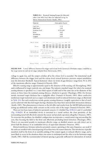
FIGURE 19.95 A small difference between the trigger and release levels (hysteresis) eliminates output instability as
the target moves in and out of range (adapted from Moldoveanu, 1993).
voltage to again rise, and the output switches off as the release level is exceeded. The intentional small
difference between the trigger level and the release level, termed hysteresis, prevents output instabilities
near the detection threshold. Typical hysteresis values (in terms of gap distance) range from 3% to 20%
of the maximum effective range (Damuck & Perrotti, 1993).
Effective sensing range is approximately equal to the diameter of the sensing coil (Koenigsburg, 1982)
and is influenced by target material, size, and shape. The industry standard target (for which the nominal
sensing distance is specified) is a 1-mm-thick square of mild steel of the same size as the diameter of the
sensor, or three times the nominal sensing distance, whichever is greater (Flueckiger, 1992). For ferrous
metals, increased target thickness has a negligible effect (Damuck & Perrotti, 1993). More conductive
nonferrous target materials such as copper and aluminum result in reduced detection range, as illustrated
in Table 19.4. For such nonferrous metals, greater sensing distances (roughly equivalent to that of steel)
can be achieved with thin-foil targets having a thickness less than their internal field attenuation distance
(Smith, 1985). This phenomenon is known as the foil effect and results from the full RF field penetration
setting up additional surface eddy currents on the reverse side of the target (Damuck & Perrotti, 1993).
There are two basic types of inductive proximity sensors: (1) shielded (Fig. 19.96(A)) and (2) unshielded
(Fig. 19.96(B)). If an unshielded device is mounted in a metal surface, the close proximity of the
surrounding metal will effectively saturate the sensor and preclude operation altogether (Swanson, 1985).
To overcome this problem, the shielded configuration incorporates a coaxial metal ring surrounding the
core, thus focusing the field to the front and effectively precluding lateral detection (Flueckiger, 1992).
There is an associated penalty in maximum effective range, as shielded sensors can only detect out to
about half the distance of an unshielded device of equivalent diameter (Swanson, 1985).
Mutual interference between inductive proximity sensors operating at the same frequency can result if
the units are installed with a lateral spacing of less than twice the sensor diameter. This interference typically
manifests itself in the form of an unstable pulsing of the output signal, or reduced effective range, and is
most likely to occur in the situation where one sensor is undamped and the other is in the hysteresis range
(Smith, 1985). Half the recommended 2d lateral spacing is generally sufficient for elimination of mutual
©2002 CRC Press LLC