
Page 492 - The Mechatronics Handbook
P. 492
0066_frame_C19 Page 114 Wednesday, January 9, 2002 5:32 PM
A B
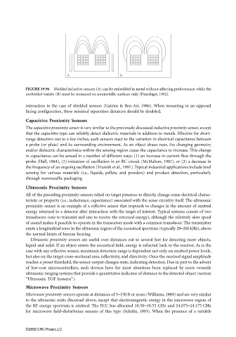
FIGURE 19.96 Shielded inductive sensors (A) can be embedded in metal without affecting performance, while the
unshielded variety (B) must be mounted on nonmetallic surfaces only (Flueckiger, 1992).
interaction in the case of shielded sensors (Gatzios & Ben-Ari, 1986). When mounting in an opposed
facing configuration, these minimal separation distances should be doubled.
Capacitive Proximity Sensors
The capacitive proximity sensor is very similar to the previously discussed inductive proximity sensor, except
that the capacitive type can reliably detect dielectric materials in addition to metals. Effective for short-
range detection out to a few inches, such sensors react to the variation in electrical capacitance between
a probe (or plate) and its surrounding environment. As an object draws near, the changing geometry
and/or dielectric characteristics within the sensing region cause the capacitance to increase. This change
in capacitance can be sensed in a number of different ways: (1) an increase in current flow through the
probe (Hall, 1984), (2) initiation of oscillation in an RC circuit (McMahon, 1987), or (3) a decrease in
the frequency of an ongoing oscillation (Vranish et al., 1991). Typical industrial applications include level
sensing for various materials (i.e., liquids, pellets, and powders) and product detection, particularly
through nonmetallic packaging.
Ultrasonic Proximity Sensors
All of the preceding proximity sensors relied on target presence to directly change some electrical charac-
teristic or property (i.e., inductance, capacitance) associated with the sense circuitry itself. The ultrasonic
proximity sensor is an example of a reflective sensor that responds to changes in the amount of emitted
energy returned to a detector after interaction with the target of interest. Typical systems consist of two
transducers (one to transmit and one to receive the returned energy), although the relatively slow speed
of sound makes it possible to operate in the transceiver mode with a common transducer. The transmitter
emits a longitudinal wave in the ultrasonic region of the acoustical spectrum (typically 20–200 kHz), above
the normal limits of human hearing.
Ultrasonic proximity sensors are useful over distances out to several feet for detecting most objects,
liquid and solid. If an object enters the acoustical field, energy is reflected back to the receiver. As is the
case with any reflective sensor, maximum detection range is dependent not only on emitted power levels,
but also on the target cross-sectional area, reflectivity, and directivity. Once the received signal amplitude
reaches a preset threshold, the sensor output changes state, indicating detection. Due in part to the advent
of low-cost microcontrollers, such devices have for most situations been replaced by more versatile
ultrasonic ranging systems that provide a quantitative indicator of distance to the detected object (section
“Ultrasonic TOF Systems”).
Microwave Proximity Sensors
Microwave proximity sensors operate at distances of 5–150 ft or more (Williams, 1989) and are very similar
to the ultrasonic units discussed above, except that electromagnetic energy in the microwave region of
the RF energy spectrum is emitted. The FCC has allocated 10.50–10.55 GHz and 24.075–24.175 GHz
for microwave field-disturbance sensors of this type (Schultz, 1993). When the presence of a suitable
©2002 CRC Press LLC