
Page 489 - The Mechatronics Handbook
P. 489
0066_frame_C19 Page 111 Wednesday, January 9, 2002 5:32 PM
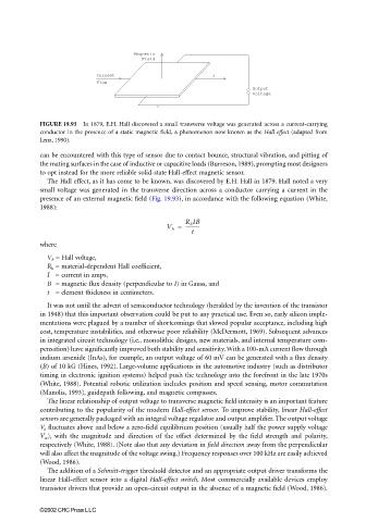
Magnetic
Field
Current I
Flow
Output
Voltage
FIGURE 19.93 In 1879, E.H. Hall discovered a small transverse voltage was generated across a current-carrying
conductor in the presence of a static magnetic field, a phenomenon now known as the Hall effect (adapted from
Lenz, 1990).
can be encountered with this type of sensor due to contact bounce, structural vibration, and pitting of
the mating surfaces in the case of inductive or capacitive loads (Burreson, 1989), prompting most designers
to opt instead for the more reliable solid-state Hall-effect magnetic sensor.
The Hall effect, as it has come to be known, was discovered by E.H. Hall in 1879. Hall noted a very
small voltage was generated in the transverse direction across a conductor carrying a current in the
presence of an external magnetic field (Fig. 19.93), in accordance with the following equation (White,
1988):
R h IB
V h = -----------
t
where
V h = Hall voltage,
R h = material-dependent Hall coefficient,
I = current in amps,
B = magnetic flux density (perpendicular to I) in Gauss, and
t = element thickness in centimeters.
It was not until the advent of semiconductor technology (heralded by the invention of the transistor
in 1948) that this important observation could be put to any practical use. Even so, early silicon imple-
mentations were plagued by a number of shortcomings that slowed popular acceptance, including high
cost, temperature instabilities, and otherwise poor reliability (McDermott, 1969). Subsequent advances
in integrated circuit technology (i.e., monolithic designs, new materials, and internal temperature com-
pensation) have significantly improved both stability and sensitivity. With a 100-mA current flow through
indium arsenide (InAs), for example, an output voltage of 60 mV can be generated with a flux density
(B) of 10 kG (Hines, 1992). Large-volume applications in the automotive industry (such as distributor
timing in electronic ignition systems) helped push the technology into the forefront in the late 1970s
(White, 1988). Potential robotic utilization includes position and speed sensing, motor commutation
(Manolis, 1993), guidepath following, and magnetic compasses.
The linear relationship of output voltage to transverse magnetic field intensity is an important feature
contributing to the popularity of the modern Hall-effect sensor. To improve stability, linear Hall-effect
sensors are generally packaged with an integral voltage regulator and output amplifier. The output voltage
V o fluctuates above and below a zero-field equilibrium position (usually half the power supply voltage
V cc ), with the magnitude and direction of the offset determined by the field strength and polarity,
respectively (White, 1988). (Note also that any deviation in field direction away from the perpendicular
will also affect the magnitude of the voltage swing.) Frequency responses over 100 kHz are easily achieved
(Wood, 1986).
The addition of a Schmitt-trigger threshold detector and an appropriate output driver transforms the
linear Hall-effect sensor into a digital Hall-effect switch. Most commercially available devices employ
transistor drivers that provide an open-circuit output in the absence of a magnetic field (Wood, 1986).
©2002 CRC Press LLC