
Page 494 - The Mechatronics Handbook
P. 494
0066_frame_C19 Page 116 Wednesday, January 9, 2002 5:32 PM
Emitter
Object
Detector
FIGURE 19.98 Diffuse-mode proximity sensors rely on energy reflected directly from the target surface.
Detection zone
Emitter
Detector
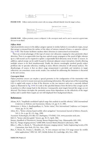
FIGURE 19.99 Diffuse proximity sensors configured in the convergent mode can be used to ascertain approximate
distance to an object.
Diffuse Mode
Optical proximity sensors in the diffuse category operate in similar fashion to retroreflective types, except
that energy is returned from the surface of the object of interest, instead of from a co-operative reflector
(Fig. 19.98). This feature facilitates random object detection in unstructured environments.
There are several advantages of this type of sensor over ultrasonic ranging for close-proximity object
detection. There is no appreciable time lag since optical energy propagates at the speed of light, whereas
up to a full second can be required to update a sequentially fired ultrasonic array of only 12 sensors. In
addition, optical energy can be easily focused to eliminate adjacent sensor interaction, thereby allowing
multiple sensors to be fired simultaneously. Finally, the shorter wavelengths involved greatly reduce
problems due to specular reflection, resulting in more effective detection of off-normal surfaces. The
disadvantage, of course, is that no direct range measurement is provided, and variations in target
reflectivity can sometimes create erratic results. One method for addressing this limitation is discussed
in the next section.
Convergent Mode
Diffuse proximity sensors can employ a special geometry in the configuration of the transmitter with
respect to the receiver to ensure more precise positioning information. The optical axis of the transmitting
LED is angled with respect to that of the detector, so the two intersect only over a narrowly defined
region as illustrated in Fig. 19.99. It is only at this specified distance from the device that a target can be
in position to reflect energy back to the detector. Consequently, most targets beyond this range are not
detected. This feature decouples the proximity sensor from dependence on the reflectivity of the target
surface and is useful where targets are not well displaced from background objects.
References
Adams, M.D., “Amplitude modulated optical range data analysis in mobile robotics,” IEEE International
Conference on Robotics and Automation, Atlanta, GA, pp. 8–13, 1993.
Aloimonos, J., Weiss, I., Bandyopadhyay, A., “Active vision,” First International Conference on Computer
Vision, pp. 35–54, 1987.
Arkin, R.C., “Motor-schema-based mobile robot navigation,” International Journal of Robotics Research,
Vol. 8., No. 4, pp. 92–112, Aug., 1989.
Ascension Technologies, P.O. Box 527, Burlington, VT 05402, USA. www.ascension-tech.com.
Ball, D., “Sensor selection guide,” Sensors, pp. 50–53, April, 1986.
Banner, Handbook of Photoelectric Sensing, Banner Engineering Corp., Minneapolis, MN, 1993.
Besl, P.J., “Range imaging sensors,” GMR-6090, General Motors Research Laboratory, 1988.
Biber, C., Ellin, S., Shenk, E., “The polaroid ultrasonic ranging system,” Audio Engineering Society, 67th
Convention, New York, NY, Oct.–Nov., 1980.
Blais, F., Rioux, M., Domey, J., Beraldin, J.A., “A very compact real time 3-D range sensor for mobile
robot applications,” SPIE Vol. 1007, Mobile Robots III, Cambridge, MA, Nov., 1988.
©2002 CRC Press LLC