
Page 493 - The Mechatronics Handbook
P. 493
0066_frame_C19 Page 115 Wednesday, January 9, 2002 5:32 PM
target reflects sufficient energy from the transmitting antenna back to a separate receiving antenna (see
Fig. 19.68 in section “Microwave Range Sensors”), the output changes state to indicate an object is present
within the field of view. An alternative configuration employing a single transmit/receive antenna mon-
itors the Doppler shift induced by a moving target to detect relative motion as opposed to presence.
These sensors are usually larger than inductive and capacitive sensors, and they are best suited to detect
larger objects.
Optical Proximity Sensors
Optical (photoelectric) sensors commonly employed in industrial applications can be broken down into
three basic groups: (1) opposed, (2) retroreflective, and (3) diffuse. (The first two of these categories are
not really “proximity” sensors in the strictest sense of the terminology.) Effective ranges vary from a few
inches out to several hundred feet. Common robotic applications include floor sensing, navigational
referencing, and collision avoidance. Industrial applications include sensing presence at a given maximum
range (for counting, or to work on a part), sensing intrusion for safety systems, alignment, etc. Modulated
near-infrared energy is typically employed to reduce the effects of ambient lighting, thus achieving the
required signal-to-noise ratio for reliable operation. Visible-red wavelengths are sometimes used to assist
in installation alignment and system diagnostics.
Actual performance depends on several factors. Effective range is a function of the physical character-
istics (i.e., size, shape, reflectivity, and material) of the object to be detected, its speed and direction of
motion, the design of the sensor, and the quality and quantity of energy it radiates or receives. Repeatability
in detection is based on the size of the target object, changes in ambient conditions, variations in reflectivity
or other material characteristics of the target, and the stability of the electronic circuitry itself. Unique
operational characteristics of each particular type can often be exploited to optimize performance in
accordance with the needs of the application.
Opposed Mode
Commonly called an “electric eye” at the time, the first of these categories was introduced into a variety
of applications back in the early 1950s, to include parts counters, automatic door openers, annunciators,
and security systems. Separate transmitting and receiving elements are physically located on either side
of the region of interest; the transmitter emits a beam of light, often supplied in more recent configurations
by an LED that is focused onto a photosensitive receiver. Any object passing between the emitter and
receiver breaks the beam, disrupting the circuit. Effective ranges of hundreds of feet or more are routinely
possible and often employed in security applications.
Retroreflective Mode
Retroreflective sensors evolved from the opposed variety through the use of a mirror to reflect the emitted
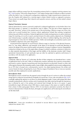
energy back to a detector located directly alongside the transmitter. Corner-cube retroreflectors (Fig. 19.97)
eventually replaced the mirrors to cut down on critical alignment needs. Corner-cube prisms have three
mutually perpendicular reflective surfaces and a hypotenuse face; light entering through the hypotenuse
face is reflected by each of the surfaces and returned back through the face to its source. A good
retroreflective target will return about 3000 times as much energy to the sensor as would be reflected
from a sheet of white typing paper (Banner, 1993). In most factory automation scenarios, the object of
interest is detected when it breaks the beam, although some applications call for placing the retroreflector
on the item itself.
Emitter
Retroreflector
Detector
FIGURE 19.97 Corner-cube retroreflectors are employed to increase effective range and simplify alignment
(adapted from Banner, 1993).
©2002 CRC Press LLC