
Page 490 - The Mechatronics Handbook
P. 490
0066_frame_C19 Page 112 Wednesday, January 9, 2002 5:32 PM
R p
Oscillator Coil Threaded Cylinder
Oscillator Trigger
Oscillator
Response Field C Equivalent L p
Demodulator Amplifier Circuit
Epoxied Resin
A B
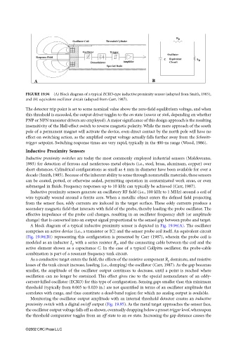
FIGURE 19.94 (A) Block diagram of a typical ECKO-type inductive proximity sensor (adapted from Smith, 1985),
and (B) equivalent oscillator circuit (adapted from Carr, 1987).
The detector trip point is set to some nominal value above the zero-field equilibrium voltage, and when
this threshold is exceeded, the output driver toggles to the on state (source or sink, depending on whether
PNP or NPN transistor drivers are employed). A major significance of this design approach is the resulting
insensitivity of the Hall-effect switch to reverse magnetic polarity. While the mere approach of the south
pole of a permanent magnet will activate the device, even direct contact by the north pole will have no
effect on switching action, as the amplified output voltage actually falls further away from the Schmitt-
trigger setpoint. Switching response times are very rapid, typically in the 400-ns range (Wood, 1986).
Inductive Proximity Sensors
Inductive proximity switches are today the most commonly employed industrial sensors (Moldoveanu,
1993) for detection of ferrous and nonferrous metal objects (i.e., steel, brass, aluminum, copper) over
short distances. Cylindrical configurations as small as 4 mm in diameter have been available for over a
decade (Smith, 1985). Because of the inherent ability to sense through nonmetallic materials, these sensors
can be coated, potted, or otherwise sealed, permitting operation in contaminated work areas, or even
submerged in fluids. Frequency responses up to 10 kHz can typically be achieved (Carr, 1987).
Inductive proximity sensors generate an oscillatory RF field (i.e., 100 kHz to 1 MHz) around a coil of
wire typically wound around a ferrite core. When a metallic object enters the defined field projecting
from the sensor face, eddy currents are induced in the target surface. These eddy currents produce a
secondary magnetic field that interacts with field of the probe, thereby loading the probe oscillator. The
effective impedance of the probe coil changes, resulting in an oscillator frequency shift (or amplitude
change) that is converted into an output signal proportional to the sensed gap between probe and target.
A block diagram of a typical inductive proximity sensor is depicted in Fig. 19.94(A). The oscillator
comprises an active device (i.e., a transistor or IC) and the sensor probe coil itself. An equivalent circuit
(Fig. 19.94(B)) representing this configuration is presented by Carr (1987), wherein the probe coil is
modeled as an inductor L p with a series resistor R p , and the connecting cable between the coil and the
active element shown as a capacitance C. In the case of a typical Collpitts oscillator, the probe-cable
combination is part of a resonant frequency tank circuit.
As a conductive target enters the field, the effects of the resistive component R p dominate, and resistive
losses of the tank circuit increase, loading (i.e., damping) the oscillator (Carr, 1987). As the gap becomes
smaller, the amplitude of the oscillator output continues to decrease, until a point is reached where
oscillation can no longer be sustained. This effect gives rise to the special nomenclature of an eddy-
current-killed oscillator (ECKO) for this type of configuration. Sensing gaps smaller than this minimum
threshold (typically from 0.005 to 0.020 in.) are not quantified in terms of an oscillator amplitude that
correlates with range, and thus constitute a dead-band region for which no analog output is available.
Monitoring the oscillator output amplitude with an internal threshold detector creates an inductive
proximity switch with a digital on/off output (Fig. 19.95). As the metal target approaches the sensor face,
the oscillator output voltage falls off as shown, eventually dropping below a preset trigger level, whereupon
the threshold comparator toggles from an off state to an on state. Increasing the gap distance causes the
©2002 CRC Press LLC