
Page 487 - The Mechatronics Handbook
P. 487
0066_frame_C19 Page 109 Wednesday, January 9, 2002 5:32 PM
Wiper
Output
Voltage
Potentiometer Wires Displacement
A B
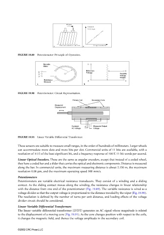
FIGURE 19.89 Potentiometer: Principle of Operation.
Movable 1
Slider
Reference 2
1
2 Voltage Variable
3 Voltage
Output
Resistance
Element 3 3
A B
FIGURE 19.90 Potentiometer: Circuit Representation.
FIGURE 19.91 Linear Variable Differential Transformer.
These sensors are suitable to measure small ranges, in the order of hundreds of millimeters. Larger wheels
can accommodate more slots and more bits per slot. Commercial units of 11 bits are available, with a
resolution of ±1/2 of the least significant bit, and a frequency response of 100 K 11-bit words per second.
Linear Optical Encoders. These are the same as angular encoders, except that instead of a coded wheel,
they have a coded bar and a slider that carries the optical and electronic components. Distance is measured
along the bar. In commercial units, the maximum measuring distance is about 2.150 m, the maximum
resolution 0.08 µm, and the maximum operating speed 508 mm/s.
Potentiometers
Potentiometers are variable electrical resistance transducers. They consist of a winding and a sliding
contact. As the sliding contact moves along the winding, the resistance changes in linear relationship
with the distance from one end of the potentiometer (Fig. 19.89). The variable resistance is wired as a
voltage divider so that the output voltage is proportional to the distance traveled by the wiper (Fig. 19.90).
The resolution is defined by the number of turns per unit distance, and loading effects of the voltage
divider circuit should be considered.
Linear Variable Differential Transformers
The linear variable differential transformer (LVDT) generates an AC signal whose magnitude is related
to the displacement of a moving core (Fig. 19.91). As the core changes position with respect to the coils,
it changes the magnetic field, and thence the voltage amplitude in the secondary coil.
©2002 CRC Press LLC