
Page 483 - The Mechatronics Handbook
P. 483
0066_frame_C19 Page 105 Wednesday, January 9, 2002 5:32 PM
precisely determine their respective coordinates in the difference-image arrays. A range vector to the
LED can then be easily calculated, based on the lateral separation of the dots as perceived by the two
cameras. This technique establishes the actual location of the manipulator in the reference frame of the
robot. Experimental results indicated a 2-in. accuracy with a 0.2-in. repeatability at a distance of approx-
imately 2 ft (Kilough and Hamel, 1989).
A near-infrared solid-state laser mounted on a remote tripod was then used by the operator to designate
a target of interest within the video image of one of the cameras. The same technique described above
was repeated, only this time the imaging system toggled the laser power on and off. A subsequent
differencing operation enabled calculation of a range vector to the target, also in the robot’s reference
frame. The difference in location of the gripper and the target object could then be used to effect both
platform and arm motion. The imaging processes would alternate in near-real-time for the gripper and
the target, enabling the HERMIES robot to drive over and grasp a randomly designated object under
continuous closed-loop control.
Structured Light
Ranging systems that employ structured light are a further refined case of active triangulation. A pattern of
light (either a line, a series of spots, or a grid pattern) is projected onto the object surface while the camera
observes the pattern from its offset vantage point. Range information manifests itself in the distortions
visible in the projected pattern due to variations in the depth of the scene. The use of these special lighting
effects tends to reduce the computational complexity and improve the reliability of three-dimensional
object analysis (Jarvis, 1983b; Vuylsteke et al., 1990). The technique is commonly used for rapid extraction
of limited quantities of visual information of moving objects (Kent, 1985), and thus lends itself well to
collision avoidance applications. Besl (1988) provides a good overview of structured-light illumination
techniques, while Vuylsteke et al. (1990) classify the various reported implementations according to the
following characteristics:
• The number and type of sensors
• The type of optics (i.e., spherical or cylindrical lens, mirrors, multiple apertures)
• The dimensionality of the illumination (i.e., point or line)
• Degrees of freedom associated with scanning mechanism (i.e., zero, one, or two)
• Whether or not the scan position is specified (i.e., the instantaneous scanning parameters are not
needed if a redundant sensor arrangement is incorporated)
The most common structured-light configuration entails projecting a line of light onto a scene, originally
introduced by P. Will and K. Pennington of IBM Research Division Headquarters, Yorktown Heights,
NY (Schwartz, undated). Their system created a plane of light by passing a collimated incandescent
source through a slit, thus projecting a line across the scene of interest. (More recent systems create the
same effect by passing a laser beam through a cylindrical lens or by rapidly scanning the beam in one
dimension.) Where the line intersects an object, the camera view will show displacements in the light
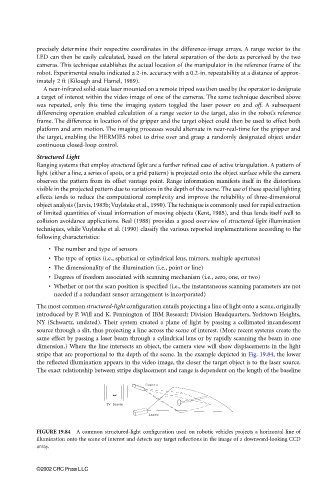
stripe that are proportional to the depth of the scene. In the example depicted in Fig. 19.84, the lower
the reflected illumination appears in the video image, the closer the target object is to the laser source.
The exact relationship between stripe displacement and range is dependent on the length of the baseline
Camera
TV Image
Laser
FIGURE 19.84 A common structured-light configuration used on robotic vehicles projects a horizontal line of
illumination onto the scene of interest and detects any target reflections in the image of a downward-looking CCD
array.
©2002 CRC Press LLC