
Page 66 - The Mechatronics Handbook
P. 66
do not have any significant actuation dynamics, and since the inertia of the moving member is usually
small, the actuator bandwidth is typically quite large, on the order of a kilohertz.
The maximum achievable stroke for normal configuration actuators is limited by the elastic region of the
flexure suspension and additionally by the dependence of actuation force on plate separation, as given by the
above stated equations. According to Fearing, a typical stroke for a surface micromachined normal config-
uration actuator is on the order of a couple of microns. The achievable displacement can be increased by
forming a stack of normal-configuration electrostatic actuators in series, as proposed by Bobbio et al. [8,9].
The typical stroke of a surface micromachined comb actuator is on the order of a few microns, though
sometimes less. The maximum achievable stroke in a comb drive is limited primarily by the mechanics
of the flexure suspension. The suspension should be compliant along the direction of actuation to enable
increased displacement, but must be stiff orthogonal to this direction to avoid parallel plate contact due
to misalignment. These modes of behavior are unfortunately coupled, so that increased compliance along
the direction of motion entails a corresponding increase in the orthogonal direction. The net effect is that
increased displacement requires increased plate separation, which results in decreased overall force.
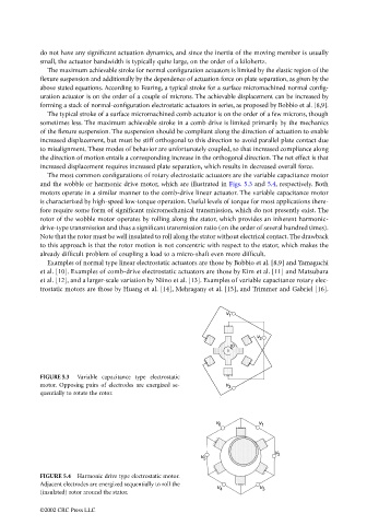
The most common configurations of rotary electrostatic actuators are the variable capacitance motor
and the wobble or harmonic drive motor, which are illustrated in Figs. 5.3 and 5.4, respectively. Both
motors operate in a similar manner to the comb-drive linear actuator. The variable capacitance motor
is characterized by high-speed low-torque operation. Useful levels of torque for most applications there-
fore require some form of significant micromechanical transmission, which do not presently exist. The
rotor of the wobble motor operates by rolling along the stator, which provides an inherent harmonic-
drive-type transmission and thus a significant transmission ratio (on the order of several hundred times).
Note that the rotor must be well insulated to roll along the stator without electrical contact. The drawback
to this approach is that the rotor motion is not concentric with respect to the stator, which makes the
already difficult problem of coupling a load to a micro-shaft even more difficult.
Examples of normal type linear electrostatic actuators are those by Bobbio et al. [8,9] and Yamaguchi
et al. [10]. Examples of comb-drive electrostatic actuators are those by Kim et al. [11] and Matsubara
et al. [12], and a larger-scale variation by Niino et al. [13]. Examples of variable capacitance rotary elec-
trostatic motors are those by Huang et al. [14], Mehragany et al. [15], and Trimmer and Gabriel [16].
FIGURE 5.3 Variable capacitance type electrostatic
motor. Opposing pairs of electrodes are energized se-
quentially to rotate the rotor.
FIGURE 5.4 Harmonic drive type electrostatic motor.
Adjacent electrodes are energized sequentially to roll the
(insulated) rotor around the stator.
©2002 CRC Press LLC