
Page 689 - The Mechatronics Handbook
P. 689
simplification is essential. When we draw a block diagram of a system we are dividing the system’s
behavior into a set of defined elements with modeled behavior and a known set of interactions between
those elements, which is itself amenable to analysis. This role of modeling would lead us to select modeling
techniques that allow us to divide the model into portions that can be independently tackled by inde-
pendent engineers. For example, systems of linear differential equations may give us great insight into
the fundamental modes of a system, but give us little insight on how to divide a design problem among
members of a team. However, a block diagram, a class diagram, or a data flow diagram provides clear
interfaces between elements that allow for subdivision.
Insights
Regarding insights into the behavior of the system, different models provide different types of insights.
Signal flow graphs of electromechanical systems show the presence of feedback loops that stabilize or
destabilize the system. Differential equations provide insights regarding the time scales of various behaviors
and the relative importance of various factors as well as providing estimates of the validity of simplifying
assumptions. Similarly, sequence and timing diagrams can provide insight regarding the processing power
required to meet timing requirements for various use cases. In each case the model provides insights into
the problem or the characteristics of a proposed solution by bringing into focus certain aspects of the
modeled system while hiding others from view.
Analogies
Related to the insights a model can give us regarding the system under consideration are the insights
that a model can provide in allowing us to see similarities to other systems that we or others have
seen before. In this regard, modeling techniques that use analogies between various domains can be
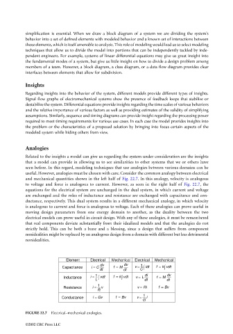
useful. However, analogies must be chosen with care. Consider the common analogy between electrical
and mechanical quantities shown in the left half of Fig. 22.7. In this analogy, velocity is analogous
to voltage and force is analogous to current. However, as seen in the right half of Fig. 22.7, the
equations for the electrical system are unchanged in the dual system, in which current and voltage
are exchanged and the roles of inductance and resistance are exchanged with capacitance and con-
ductance, respectively. This dual system results in a different mechanical analogy, in which velocity
is analogous to current and force is analogous to voltage. Each of these analogies can prove useful in
moving design parameters from one energy domain to another, as the duality between the two
electrical models can prove useful in circuit design. With any of these analogies, it must be remembered
that real components deviate substantially from their idealized models and that the analogies do not
strictly hold. This can be both a bane and a blessing, since a design that suffers from component
nonidealities might be replaced by an analogous design from a domain with different but less detrimental
nonidealities.
Element Electrical Mechanical Electrical Mechanical
dv dv 1
Capacitance i = C f = M v = ∫ idt f = k ∫ vdt
dt dt C
1 di dv
Inductance i = ∫ vdt f = k ∫ vdt v = L f = M
L dt dt
1
Resistance i = v v = Ri f = Bv
R 1
Conductance i = Gv f = Bv v = i
G
FIGURE 22.7 Electrical–mechanical analogies.
©2002 CRC Press LLC