
Page 685 - The Mechatronics Handbook
P. 685
Maint. Status
Maint. User
Commands Authorization
Network
Print Requests Status Requests
Printer
Request
Print Data Acknowledge
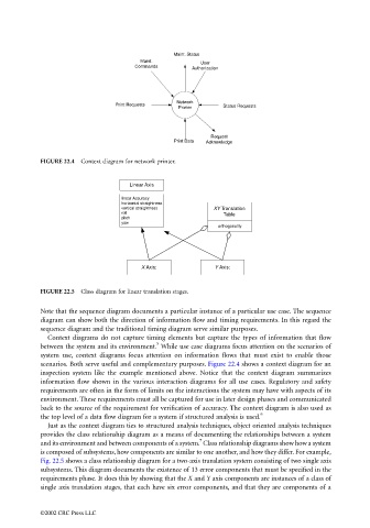
FIGURE 22.4 Context diagram for network printer.
Linear Axis
linear Accuracy
horizontal straightness
vertical straightness XY Translation
roll Table
pitch
yaw
orthogonality
X Axis: Y Axis:
FIGURE 22.5 Class diagram for linear translation stages.
Note that the sequence diagram documents a particular instance of a particular use case. The sequence
diagram can show both the direction of information flow and timing requirements. In this regard the
sequence diagram and the traditional timing diagram serve similar purposes.
Context diagrams do not capture timing elements but capture the types of information that flow
5
between the system and its environment. While use case diagrams focus attention on the scenarios of
system use, context diagrams focus attention on information flows that must exist to enable those
scenarios. Both serve useful and complementary purposes. Figure 22.4 shows a context diagram for an
inspection system like the example mentioned above. Notice that the context diagram summarizes
information flow shown in the various interaction diagrams for all use cases. Regulatory and safety
requirements are often in the form of limits on the interactions the system may have with aspects of its
environment. These requirements must all be captured for use in later design phases and communicated
back to the source of the requirement for verification of accuracy. The context diagram is also used as
6
the top level of a data flow diagram for a system if structured analysis is used.
Just as the context diagram ties to structured analysis techniques, object oriented analysis techniques
provides the class relationship diagram as a means of documenting the relationships between a system
7
and its environment and between components of a system. Class relationship diagrams show how a system
is composed of subsystems, how components are similar to one another, and how they differ. For example,
Fig. 22.5 shows a class relationship diagram for a two-axis translation system consisting of two single axis
subsystems. This diagram documents the existence of 13 error components that must be specified in the
requirements phase. It does this by showing that the X and Y axis components are instances of a class of
single axis translation stages, that each have six error components, and that they are components of a
©2002 CRC Press LLC