
Page 686 - The Mechatronics Handbook
P. 686
system that adds a single additional error. By documenting relationships such as composition and inher-
itance, requirements and the interdependence of requirements can be represented in a compact and
comprehensible way.
One key aspect of the requirements definition phase is the importance of defining requirements without
specifying a preferred solution embodiment. Hence, modeling methods should be chosen to document
these requirements and their intrinsic relationships without implying a particular solution.
Phase 2
In the concept generation phase, our objective is to generate multiple design concepts that might satisfy
the requirements identified in phase 1. Here we need modeling techniques that allow us to describe
possible solutions with varying levels of detail dependent on the degree of detail needed to document
the key elements of the concept. Since individual concepts generated in this phase may only satisfy some
portions of the design requirements, it is critical that modeling at this point allow for partial descriptions
of embodiments and for the easy combination of design concepts. For this reason, our models must
clearly document the portions of the requirements satisfied as well as any unspecified parameters or
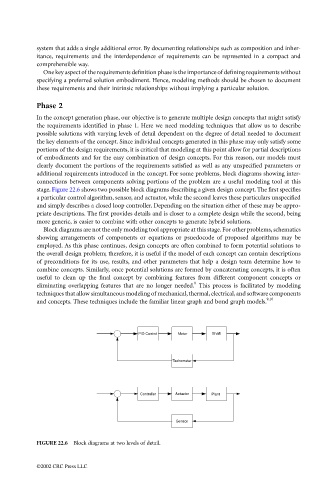
additional requirements introduced in the concept. For some problems, block diagrams showing inter-
connections between components solving portions of the problem are a useful modeling tool at this
stage. Figure 22.6 shows two possible block diagrams describing a given design concept. The first specifies
a particular control algorithm, sensor, and actuator, while the second leaves these particulars unspecified
and simply describes a closed loop controller. Depending on the situation either of these may be appro-
priate descriptions. The first provides details and is closer to a complete design while the second, being
more generic, is easier to combine with other concepts to generate hybrid solutions.
Block diagrams are not the only modeling tool appropriate at this stage. For other problems, schematics
showing arrangements of components or equations or psuedocode of proposed algorithms may be
employed. As this phase continues, design concepts are often combined to form potential solutions to
the overall design problem; therefore, it is useful if the model of each concept can contain descriptions
of preconditions for its use, results, and other parameters that help a design team determine how to
combine concepts. Similarly, once potential solutions are formed by concatenating concepts, it is often
useful to clean up the final concept by combining features from different component concepts or
8
eliminating overlapping features that are no longer needed. This process is facilitated by modeling
techniques that allow simultaneous modeling of mechanical, thermal, electrical, and software components
and concepts. These techniques include the familiar linear graph and bond graph models. 9,10
PID Control Motor Shaft
Tachometer
Controller Actuator Plant
Sensor
FIGURE 22.6 Block diagrams at two levels of detail.
©2002 CRC Press LLC