
Page 683 - The Mechatronics Handbook
P. 683
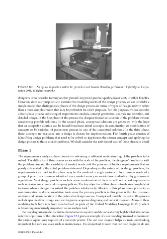
FIGURE 22.1  An optical inspection system for printed circuit boards. (Used by permission ” CyberOptics Corpo-
                                 ration 2001, all rights reserved.)
                                 designers or to describe techniques that provide improved product quality, lower cost, or other benefits.
                                 However, since our purpose is to examine the modeling needs of the design process, we can consider a
                                 simple model that distinguishes phases of the design process in terms of types of design activity rather
                                 than a more complex model that may be preferable for other purposes. For this purpose, we can consider
                                 a four-phase process consisting of requirements analysis, concept generation, analysis and selection, and
                                 detailed design. In the first phase of this process the designer focuses on analysis of the problem without
                                 considering possible solutions. In the second phase, conceptual solutions are generated with the hope
                                 that an acceptable solution can be found from these initial concepts via combination or modification of
                                 concepts or by variation of parameters present in one of the conceptual solutions. In the third phase,
                                 these concepts are evaluated and a design is chosen for implementation. The fourth phase consists of
                                 identifying design problems that need to be solved to implement the chosen concept and applying the
                                 design process to those smaller problems. We shall consider the activities of each of these phases in detail.

                                 Phase 1
                                 The requirements analysis phase consists in obtaining a sufficient understanding of the problem to be
                                 solved. The difficulty of this process varies with the scale of the problem, the designers’ familiarity with
                                 the problem domain, the variability of market needs, and the presence of hidden requirements that are
                                 poorly articulated in the initial problem statement. Depending on the nature of the design problem, the
                                 requirements identified in this phase may be the needs of a single customer, the common needs of a
                                 group of potential customers identified via a market survey, or societal needs identified by government
                                 regulations. Most design problems include some combination of these as well as internal requirements
                                 such as design guidelines and company policies. The key objective of this phase is to obtain enough detail
                                 to know when a design has solved the problem satisfactorily. Models in this phase serve primarily as
                                 communication and documentation tools since the primary problem in this phase is the clear commu-
                                 nication and documentation of the criteria for design success. Examples of models that aid in this process
                                 include specification listings, use case diagrams, sequence diagrams, and context diagrams. Many of these
                                 modeling tools have now been standardized as parts of the Unified Modeling Language (UML), which
                                                                           4
                                 is becoming increasingly important as an analysis tool.
                                   Use case diagrams model the interactions between a system and its users at a very high level of abstraction
                                 in terms of purpose of the interaction. Figure 22.2 gives an example of a use case diagram used to document
                                 the various operations required of a network printer. The use case diagram helps us avoid overlooking
                                 important but rare use cases such as maintenance. It is important to note that use case diagrams do not

                                 ©2002 CRC Press LLC