
Page 679 - The Mechatronics Handbook
P. 679
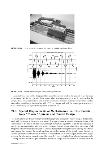
FIGURE 21.24  Linear motor. The magnets that cause the cogging are clearly visible.


                                 FIGURE 21.25  Position and error signal during learning of the LFFC.

                                   A mechatronic view on this design problem raises the question whether it is possible to use the same
                                 techniques to build a less expensive linear motor, when maximum accuracy is not the main goal of the
                                 design. It has been demonstrated that a motor constructed with less expensive components and less
                                 demanding assembly specifications but with LFFC can compete well with the more expensive construc-
                                 tion. The accuracy can typically be improved by a factor 10.

                                 21.5 Special Requirements of Mechatronics that Differentiate
                                         from “Classic” Systems and Control Design

                                 The main difference between “ordinary controller design” and mechatronic system design is that the latter
                                 deals with the design of the system as a whole. This approach can be considered as optimization of all
                                 components of the system simultaneously, although there are no algorithms to do this automatically. In
                                 practice the problem is often split into smaller problems that can be optimized. After integration of all
                                 the partial solutions a suboptimal system is achieved that can be further optimized by retuning the different
                                 parts, taking into account the already available intermediate design of the overall system. In order to
                                 achieve optimization of the system as a whole, it is desired that the mechanical part, where power plays a
                                 role, and the information processing part (the controller) can be simulated and adjusted simultaneously.
                                 This requires that mechanical parameters like masses and compliances be available in simulations of the

                                 ©2002 CRC Press LLC