
Page 677 - The Mechatronics Handbook
P. 677
be in counter phase with the forces of the waves. In order to make the system effective for varying
frequencies of the waves, the water flow between the two tanks should be controlled. For fast ships mostly
stabilizing fins are used. These are a kind of actively controlled “wings” that generate the moments needed
to counteract the moments of the waves. The fins not only influence the roll motions but also have
influence on the heading. On the other hand, the rudder not only influences the heading but also induces
roll. In control engineering terms this leads to a multivariable system that requires a multivariable
controller design for optimum performance. In practice such a multivariable system is seldom seen and
two separate control systems are used.
Another approach is to use only one of the actuators (rudder or fins) to achieve course control and
roll reduction. Because the frequencies of the roll motions are outside the bandwidth of the course-
control system this is possible. The rudder is most suited as actuator. An additional advantage for naval
ships is that removing the fins will reduce the underwater noise of the vessel.
Redesigning the course controller in order to stabilize the roll as well, demonstrates the feasibility of
this approach, but also makes clear that the “process”—the ship—should be modified. The most impor-
tant modification is needed for the steering machine. The maximum speed of the steering machine
appears to be the limiting factor for such a system (it should increase from the commonly used values
of 3–7∞/s to 20–25∞/s). By means of dynamic simulations the demands for the steering machine can be
found in terms of the maximum speed of the steering machine and the maximum time constant that is
allowed for reaching this speed. This requires reengineering of the hydraulic steering machine. A step
further would be to consider also changes in the shape of the ship, in order to optimize the parameters
that determine the effectiveness of the rudder roll stabilization system.
In order to decide whether this new solution is better, it should be evaluated whether the redesigned
steering machine is less expensive than the original rudder and fin actuators. These design issues have
to be solved in a very early stage of the design. Rudder roll stabilization has been successfully applied on
15
naval as well as merchant marine ships (Van Amerongen, Van der Klugt, and Van Nauta Lemke ).
Compensation of Nonlinear Effects in a Linear Motor
Many mechanical systems suffer from nonlinear effects that limit the accuracy that can be achieved.
Friction and cogging are two examples. A (linear) feedback controller can diminish the influence of non-
linearities, but complete compensation may be difficult. For systems that perform repetitive motions, an
16
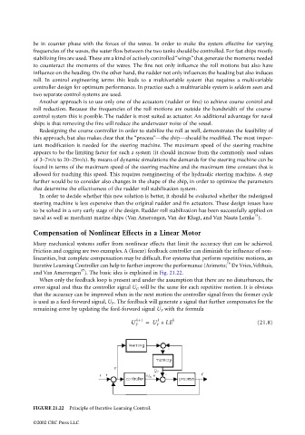
Iterative Learning Controller can help to further improve the performance (Arimoto; De Vries, Velthuis,
17
and Van Amerongen ). The basic idea is explained in Fig. 21.22.
When only the feedback loop is present and under the assumption that there are no disturbances, the
error signal and thus the controller signal U C will be the same for each repetitive motion. It is obvious
that the accuracy can be improved when in the next motion the controller signal from the former cycle
is used as a feed-forward signal, U F . The feedback will generate a signal that further compensates for the
remaining error by updating the feed-forward signal U F with the formula
k+1 k k
U F = U F + LE (21.8)
FIGURE 21.22 Principle of Iterative Learning Control.
©2002 CRC Press LLC