
Page 675 - The Mechatronics Handbook
P. 675
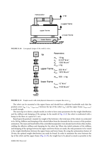
FIGURE 21.18  Conceptual design of the mobile robot.


                                 FIGURE 21.19  Simple model with ideal physical elements to compute the error e tip .
                                   The robot can be mounted at the upper frame and should have sufficient bandwidth such that the
                                 position error (e tip  = z tip  - z upper frame ) between the tip of the robot (z tip ) and the upper frame (z upper frame )
                                 is small enough.
                                   The next step is to derive a simple model, in order to have some parameters for the weight distribution
                                 and the stiffness and damping of the springs. In the model of Fig. 21.22 the robot is confronted with a
                                 bump in the floor at a speed of 1 m/s.
                                   Based upon the payload—mainly the weight of the batteries—the total mass of the vehicle was estimated
                                 to be 500 kg. Stiffness and damping of the wheels follow from the demands for the accuracy of the position
                                 estimation. The mass and bandwidth of the controlled manipulator were already known from other studies,
                                 yielding the effective stiffness and damping for the robot tip. When also initial estimates of the stiffness
                                 and damping of the springs between the upper and lower frame are made, the only parameter to be varied
                                 is the weight distribution between the upper frame and lower frame. By using the optimization feature of
                                 20-sim, the optimal weight distribution can easily be found. In order to minimize the error between the
                                 tip of the robot and the upper frame (Fig. 21.19), the weight has to be placed as much as possible in the

                                 ©2002 CRC Press LLC