
Page 671 - The Mechatronics Handbook
P. 671
models can also describe many mechatronic systems. A mechatronic system mostly consists of an actuator,
some form of transmission, and a load. A fourth-order model can properly describe such a system. The
performance-limiting factor in these systems is the resonance frequency. A combination of position and
tacho feedback (basically a PD controller) can be applied here as well. But due to the resonant poles proper
selection of the signals to be used in the feedback is essential. Efforts have been made (Groenhuis; 13
2
3
Coelingh; Coelingh, De Vries, and Van Amerongen ) to derive recipes for tuning such systems, in addition
to selecting the proper feedback signals. Computer support tools are essential to enable less experienced
2
14
designers to use these recipes (Van Amerongen, Coelingh, and De Vries ). Coelingh and Coelingh, De
3
Vries, and Van Amerongen describe a structural design method for mechatronic systems. The method
starts with reducing the conceptual design to a fourth-order model that represents the dominant prop-
erties of the system in terms of the total mass to be moved and the dominant stiffness. This model still
has physical meaningful parameters. In this model appropriate sensors are chosen, as well as a path
generator. In the conceptual design phase a simple controller is developed and mechanical properties are
changed, if necessary. Then a more detailed design phase follows where also parameter uncertainties are
taken into account.
Servo System Design
Here we will consider some simple aspects of the design of a servo system in order to illustrate the
advantage of the use of physical models and to illustrate the need for an integrated design approach. We
consider the model discussed before, a load driven by an electric motor, through a flexible transmission.
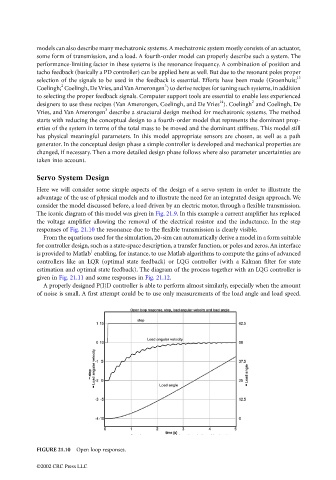
The iconic diagram of this model was given in Fig. 21.9. In this example a current amplifier has replaced
the voltage amplifier allowing the removal of the electrical resistor and the inductance. In the step
responses of Fig. 21.10 the resonance due to the flexible transmission is clearly visible.
From the equations used for the simulation, 20-sim can automatically derive a model in a form suitable
for controller design, such as a state-space description, a transfer function, or poles and zeros. An interface
1
is provided to Matlab enabling, for instance, to use Matlab algorithms to compute the gains of advanced
controllers like an LQR (optimal state feedback) or LQG controller (with a Kalman filter for state
estimation and optimal state feedback). The diagram of the process together with an LQG controller is
given in Fig. 21.11 and some responses in Fig. 21.12.
A properly designed P(I)D controller is able to perform almost similarly, especially when the amount
of noise is small. A first attempt could be to use only measurements of the load angle and load speed.
FIGURE 21.10 Open loop responses.
©2002 CRC Press LLC