
Page 971 - The Mechatronics Handbook
P. 971
0066_Frame_C32.fm Page 21 Wednesday, January 9, 2002 7:54 PM
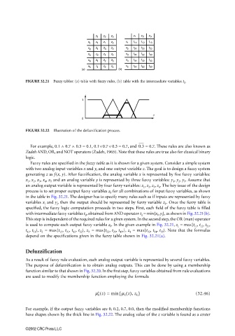
y 1 y 2 y 3 y 1 y 2 y 3
x 1 z 1 z 1 z 2 x 1 t 11 t 12 t 13
x 2 z 1 z 3 z 3 x 2 t 21 t 22 t 23
x 3 z 2 z 4 z 4 x 3 t 31 t 32 t 33
x 4 z 1 z 2 z 3 x 4 t 41 t 42 t 43
x 5 z 1 z 2 z 4 x 5 t 51 t 52 t 53
(a) (b)
FIGURE 32.21 Fuzzy tables: (a) table with fuzzy rules, (b) table with the intermediate variables t ij .
1
z
0
FIGURE 32.22 Illustration of the defuzzification process.
For example, 0.1 ∧ 0.7 ∧ 0.3 = 0.1, 0.1∨0.7 ∨ 0.3 = 0.7, and 0.3 = 0.7. These rules are also known as
Zadeh AND, OR, and NOT operators (Zadeh, 1965). Note that these rules are true also for classical binary
logic.
Fuzzy rules are specified in the fuzzy table as it is shown for a given system. Consider a simple system
with two analog input variables x and y, and one output variable z. The goal is to design a fuzzy system
generating z as f(x, y). After fuzzification, the analog variable x is represented by five fuzzy variables:
x 1 , x 2 , x 3 , x 4 , x 5 and an analog variable y is represented by three fuzzy variables: y 1 , y 2 , y 3 . Assume that
an analog output variable is represented by four fuzzy variables: z 1 , z 2 , z 3 , z 4 . The key issue of the design
process is to set proper output fuzzy variables z k for all combinations of input fuzzy variables, as shown
in the table in Fig. 32.21. The designer has to specify many rules such as if inputs are represented by fuzzy
variables x i and y j , then the output should be represented by fuzzy variable z k . Once the fuzzy table is
specified, the fuzzy logic computation proceeds in two steps. First, each field of the fuzzy table is filled
with intermediate fuzzy variables t ij , obtained from AND operator t ij = min{x i , y j }, as shown in Fig. 32.21(b).
This step is independent of the required rules for a given system. In the second step, the OR (max) operator
is used to compute each output fuzzy variable z k . In the given example in Fig. 32.21, z 1 = max{t 11 , t 12 , t 21 ,
t 41 , t 51 }, z 2 = max{t 13 , t 31 , t 42 , t 52 }, z 3 = max{t 22 , t 23 , t 43 ,}, z 4 = max{t 32 , t 34 , t 53 }. Note that the formulas
depend on the specifications given in the fuzzy table shown in Fig. 32.21(a).
Defuzzification
As a result of fuzzy rule evaluation, each analog output variable is represented by several fuzzy variables.
The purpose of defuzzification is to obtain analog outputs. This can be done by using a membership
function similar to that shown in Fig. 32.20. In the first step, fuzzy variables obtained from rule evaluations
are used to modify the membership function employing the formula
{
∗
m k z() = min m k z(), z k } (32.46)
For example, if the output fuzzy variables are 0, 0.2, 0.7, 0.0, then the modified membership functions
have shapes shown by the thick line in Fig. 32.22. The analog value of the z variable is found as a center
©2002 CRC Press LLC