
Page 67 - Theory and Design of Air Cushion Craft
P. 67
Early air cushion theory developments 51
(<(/'////
/ / / /
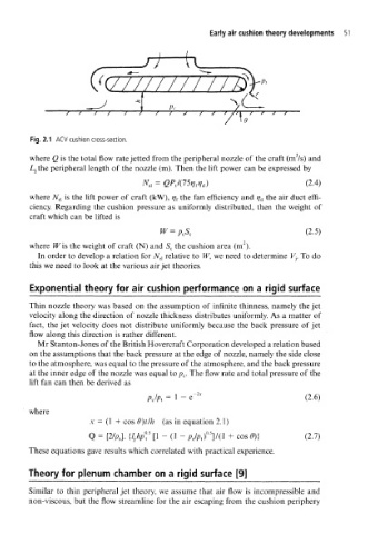
Fig. 2.1 ACV cushion cross-section.
where Q is the total flow rate jetted from the peripheral nozzle of the craft (m /s) and
Ljthe peripheral length of the nozzle (m). Then the lift power can be expressed by
= QPJ(15w A) (2.4)
N e]
where N el is the lift power of craft (kW), rj { the fan efficiency and rj d the air duct effi-
ciency. Regarding the cushion pressure as uniformly distributed, then the weight of
craft which can be lifted is
W = PcS c (2.5)
2
where W is the weight of craft (N) and S c the cushion area (m ).
In order to develop a relation for jV el relative to W, we need to determine V- r To do
this we need to look at the various air jet theories.
Exponential theory for air cushion performance on a rigid surface
Thin nozzle theory was based on the assumption of infinite thinness, namely the jet
velocity along the direction of nozzle thickness distributes uniformly. As a matter of
fact, the jet velocity does not distribute uniformly because the back pressure of jet
flow along this direction is rather different.
Mr Stanton-Jones of the British Hovercraft Corporation developed a relation based
on the assumptions that the back pressure at the edge of nozzle, namely the side close
to the atmosphere, was equal to the pressure of the atmosphere, and the back pressure
at the inner edge of the nozzle was equal to p c. The flow rate and total pressure of the
lift fan can then be derived as
= 1 - e~ Zv (2.6)
p c/p t
where
x = (1 + cos 9)tlh (as in equation 2.1)
Q = [2/AJ. {l }h£ 5 [1 - (1 - fl/p/VO + cos 0)} (2.7)
These equations gave results which correlated with practical experience.
Theory for plenum chamber on a rigid surface [9]
Similar to thin peripheral jet theory, we assume that air flow is incompressible and
non-viscous, but the flow streamline for the air escaping from the cushion periphery