
Page 69 - Theory and Design of Air Cushion Craft
P. 69
Early air cushion theory developments 53
C
(a) (b) (c)
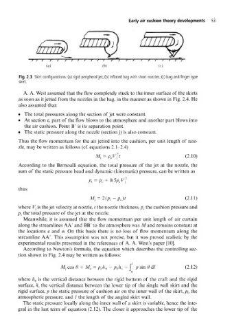
Fig. 2.3 Skirt configurations: (a) rigid peripheral jet; (b) inflated bag with short nozzles; (c) bag and finger type
skirt.
A. A. West assumed that the flow completely stuck to the inner surface of the skirts
as soon as it jetted from the nozzles in the bag, in the manner as shown in Fig. 2.4. He
also assumed that:
• The total pressures along the section of jet were constant.
• At section e, part of the flow blows to the atmosphere and another part blows into
the air cushion. Point B' is its separation point.
• The static pressure along the nozzle (section j) is also constant.
Thus the flow momentum for the air jetted into the cushion, per unit length of noz-
zle, may be written as follows (cf. equations 2.1-2 .4)
p
Mi = , V f t (2.10)
According to the Bernoulli equation, the total pressure of the jet at the nozzle, the
sum of the static pressure head and dynamic (kinematic) pressure, can be written as
thus
p e)t (2.11)
where V } is the jet velocity at nozzle, t the nozzle thickness, p c the cushion pressure and
Pi the total pressure of the jet at the nozzle.
Meanwhile, it is assumed that the flow momentum per unit length of air curtain
along the streamlines AA' and BB' to the atmosphere was M and remains constant at
the locations e and o. On this basis there is no loss of flow momentum along the
streamline A A'. This assumption was not precise, but it was proved realistic by the
experimental results presented in the references of A. A. West's paper [10].
According to Newton's formula, the equation which describes the controlling sec-
tion shown in Fig. 2.4 may be written as follows:
f /
Mj cos 9 + M e = p ch b - p Qh s — I p sin 0 d/ (2.12)
o
where h b is the vertical distance between the rigid bottom of the craft and the rigid
surface, h s the vertical distance between the lower tip of the single wall skirt and the
rigid surface, p the static pressure of cushion air on the inner wall of the skirt, p Q the
atmospheric pressure, and 7 the length of the angled skirt wall.
The static pressure locally along the inner wall of a skirt is variable, hence the inte-
gral in the last term of equation (2.12). The closer it approaches the lower tip of the