
Page 68 - Theory and Design of Air Cushion Craft
P. 68
52 Air cushion theory
is rather different from hovercraft with peripheral jets, because of its different duct
configuration.
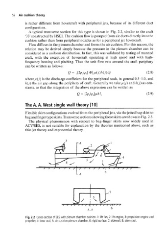
A typical transverse section for this type is shown in Fig. 2.2, similar to the craft
'33' constructed by HSEI. The cushion flow is pumped from air ducts directly into the
cushion rather than from peripheral nozzles as for a peripheral jet hovercraft.
Flow diffuses in the plenum chamber and forms the air cushion. For this reason, the
relation may be derived simply because the pressure in the plenum chamber can be
considered as a uniform distribution. In fact, this was validated by testing of manned
craft, with the exception of hovercraft operating at high speed and with high-
frequency heaving and pitching. Thus the unit flow rate around the craft periphery
can be written as follows:
Q = ,[2pM0l jii(j)h(j)dj (2.8)
where //(y) is the discharge coefficient for the peripheral seals, in general 0.5-1.0, and
h(j) the air gap along the periphery of craft. Generally we take//(y') and h(J) as con-
stants, so that the integration of the above expression can be written as
(2.9)
The A. A. West single wall theory [10]
Flexible skirt configurations evolved from the peripheral jets, via the jetted bag skirt to
bag and finger type skirts. Transverse sections showing these skirts are shown in Fig. 2.3.
The physical phenomenon with respect to bag-finger skirts now widely used in
ACV/SES, is not suitable for explanation by the theories mentioned above, such as
thin jet theory and exponential theory.
rA
/ [ / ' / / / f 6 \ / ' / / / S
4_4
Fig. 2.2 Cross-section of SES with plenum chamber cushion. 1: lift fan, 2: lift engine, 3: propulsion engine and
propeller, 4: bow seal, 5: air cushion plenum chamber, 6: rigid surface, 7: sidewall, 8: stern seal.