
Page 213 - Thomson, William Tyrrell-Theory of Vibration with Applications-Taylor _ Francis (2010)
P. 213
200 Properties of Vibrating Systems Chap. 6
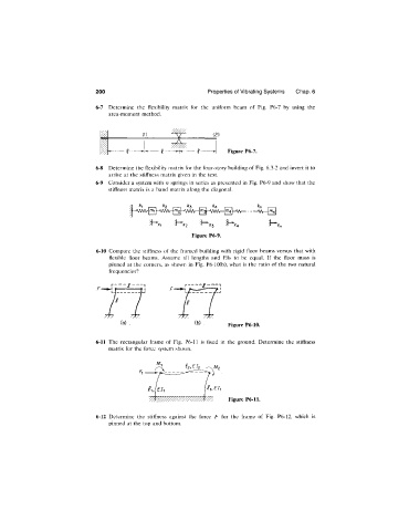
6-7 Determine the flexibility matrix for the uniform beam of Fig. P6-7 by using the
area-moment method.
1 (1) (2)
Figure P6-7.
6-8 Determine the flexibility matrix for the four-story building of Fig. 6.3-2 and invert it to
arrive at the stiffness matrix given in the text.
6-9 Consider a system with n springs in series as presented in Fig. P6-9 and show that the
stiffness matrix is a band matrix along the diagonal.
--------Q
^ X ^ '^X3 h^X4
Figure P6-9.
6-10 Compare the stiffness of the framed building with rigid floor beams versus that with
flexible floor beams. Assume all lengths and Els to be equal. If the floor mass is
pinned at the corners, as shown in Fig. P6-10(b), what is the ratio of the two natural
frequencies?
Figure P6-10.
6-11 The rectangular frame of Fig. P6-11 is fixed in the ground. Determine the stiffness
matrix for the force system shovm.
Figure P6-11.
6-12 Determine the stiffness against the force F for the frame of Fig. P6-12, which is
pinned at the top and bottom.