Page 245 - Thomson, William Tyrrell-Theory of Vibration with Applications-Taylor _ Francis (2010)
P. 245

232                                      Lagrange’s Equation   Chap. 7

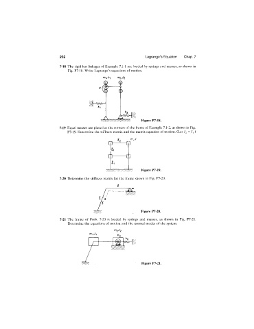
                              7-18  The rigid bar linkages of Example 7.1-1  are loaded by springs and masses, as shown in
                                  Fig.  P7-18.  Write  Lagrange’s equations of motion.


                                                                     Figure  P7-18.
                              7-19  Equal masses are placed at the corners of the frame of Example 7.1-2, as shown in Fig.
                                  P7-19.  Determine the stiffness matrix and the matrix equation of motion. (Let  I2 = l\ )


                                                      [J-     -£]


                                                    y /7 ///, 'y / / / / / / / / / /    Figure P7-19.
                              7-20  Determine  the  stiffness matrix for the  frame  shown  in  Fig.  P7-20.

                                                          £


                                                                     Figure P7-20.

                              7-21  The  frame  of  Prob.  7-20  is  loaded  by  springs  and  masses,  as  shown  in  Fig.  P7-2L
                                  Determine  the  equations of motion  and the  normal  modes of the  system.
                                                        /r72 c/2


                                                                     Figure P7-21.
   240   241   242   243   244   245   246   247   248   249   250