
Page 320 - Thomson, William Tyrrell-Theory of Vibration with Applications-Taylor _ Francis (2010)
P. 320
Sec. 10.2 Stiffness and Mass for the Beam Element 307
The preceding displacements can be considered to be the superposition of
the four shapes, labeled (Pi(x), (P2(x), cp^ix), and (pj^x), shown in Fig. 10.2-2. The
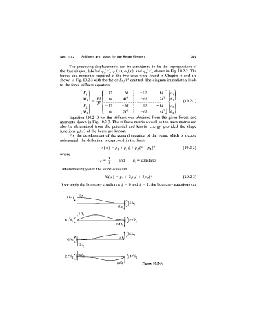
forces and moments required at the two ends were found in Chapter 6 and are
shown in Fig. 10.2-3 with the factor EI/P omitted. The diagram immediately leads
to the force-stiffness equation:
12 6/ 1 -1 2 61 '
EL 61 4/2 1 -61 2/2 (10.2-1)
-12 - 6 / i 12 -61 Vi
6/ 2/2 1 -61 4 l \ 1^2 j
2 )
Equation (10.2-1) for the stiffness was obtained from the given forces and
moments shown in Fig. 10.2-3. The stiffness matrix as well as the mass matrix can
also be determined from the potential and kinetic energy, provided the shape
functions (p^ix) of the beam are known.
For the development of the general equation of the beam, which is a cubic
polynomial, the deflection is expressed in the form
v { x ) = Pi + P 2 i + (10.2-2)
where
X
^ = j and p¿ = constants
Differentiating yields the slope equation
i e { x ) = P 2 + 2P2^ + (10.2-3)
If we apply the boundary conditions ^ = 0 and ^ = 1, the boundary equations can
Figure 10.2-3.