
Page 315 - Thomson, William Tyrrell-Theory of Vibration with Applications-Taylor _ Francis (2010)
P. 315
302 Introduction to the Finite Element Method Chap. 10
I u I
k n
-v w w ----- ^ ^F^ku
EA/i n
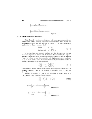
■F={FA/l)u
Figure 10.1-1.
10.1 ELEMENT STIFFNESS AND MASS
Axial element. An element with pinned ends can support only axial forces
and hence will act like a spring. Figure 10.1-1 shows a spring and a uniform rod
pinned to a stationary wall and subjected to a force F. The force-displacement
relationships for the two cases are simply
Spring f = ku
( 10.1-1)
Uniform rod
In general, these axial elements can be a part of a pin-connected structure
that allows displacement of both ends. In the finite element method, the displace
ment and force at each end of the element must be accounted for with proper sign.
Figure 10.1-2 shows an axial element labeled with displacements Wj, U2, and forces
Fj, F2, all in the positive sense. If we write the force-displacement relationship in
terms of the stiffness matrix, the equation is
( 10.1-2)
^22
The elements of the first column of the stiffness matrix represent the forces at the
two ends when = \ and U2 = 0, as shown in Fig. 10.1-3. Thus, = ku^ and
F2 = —kuy
Similarly, by letting U2 = I and = 0, we obtain, as in Fig. 10.1-4, F^ =
-ku2 and F2 = ku2. Thus, Eq. (10.1-2) becomes
(10.1-2')
1 k 2
r -^2
F F Figure 10.1-2.
pr k
—- -.... i
i/,=t
"2' Figure 10.1-3.