
Page 316 - Thomson, William Tyrrell-Theory of Vibration with Applications-Taylor _ Francis (2010)
P. 316
Sec. 10.1 Element Stiffness and Mass 303
-^2
",=0 Figure 10.1-4.
If the spring is replaced by a uniform rod, k = AE// and the equation
becomes
EA 1 - 1
I -1 1 (10.1-3)
These equations thus define the stiffness matrix for axial elements in terms of axial
coordinates and axial forces regardless of the orientation of the axial
member.
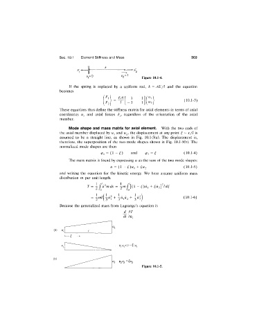
Mode shape and mass matrix for axial element. With the two ends of
the axial member displaced by W and Uj, the displacement at any point ^ = x/l \s
j
assumed to be a straight line, as shown in Fig. 10.1-5(a). The displacement is,
therefore, the superposition of the two mode shapes shown in Fig. 10.1-5(b). The
normalized mode shapes are then
= (1 - è) and <Pi = ^ (10.1-4)
The mass matrix is found by expressing u as the sum of the two mode shapes:
u = {\ - ¿)w, + ¿^2 (10.1-5)
and writing the equation for the kinetic energy. We here assume uniform mass
distribution m per unit length.
T = i f ù^mdx = i m ( [(1 - ^)ù, -f
1
( 10.1-6)
Because the generalized mass from Lagrange’s equation is
dt dU:
( a )
(b)
Figure 10.1-5.