
Page 168 - Thermal Hydraulics Aspects of Liquid Metal Cooled Nuclear Reactors
P. 168
140 Thermal Hydraulics Aspects of Liquid Metal Cooled Nuclear Reactors
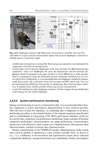
Fig. 3.4.5 Diaphragm chamber with filling and vent port before assembly (left) and PLC
screenshot of a typical pressure measurement station with pressure diaphragms connected to
multiple process connections (right).
solidification in the pressure sensing tube. Heat tracing zone separation is recommended for
components with different thermal inertia.
l Position high- and low-pressure diaphragms at the same elevation. For differential pressure
transmitters, where two diaphragms are used, the high-pressure and low-pressure dia-
phragms should be mounted at the same elevation to avoid differences in static pressure.
Prior to experimental testing, the differential pressure transmitter should anyway be zero-
set with no flow. Furthermore, it is recommended that each diaphragm chamber be indepen-
dently heat traced, with a dedicated control thermocouple and PID control loop. This is to
prevent temperature differences between the two diaphragms that could arise from a differ-
ence in thermal losses, thereby possibly influencing pressure measurements.
l Avoid LM solidification inside diaphragm chambers. Volume changes during solidification
could damage the thin-walled diaphragm.
3.4.9.4 System performance monitoring
During commissioning of a newly constructed facility, it is recommended that a base-
line component or system performance characterization is done wherever possible.
This will serve at least two functions: (i) confirming that a component or system is
performing according to the intended design or the original equipment specification
and (ii) establishment of a beginning of life (BOL) performance baseline, which can
be used for later comparison and performance monitoring. Some examples of baseline
component performance characterizations are pump performance characterization
(pump curve and efficiency), total system curve characterization, filter pressure drop
characterization, and heat exchanger duty characterization.
During commissioning of the COMPLOT facility, characterization of the system
curve proved valuable in identifying a valve actuator assembly fault. As shown in
Fig. 3.4.6, a difference in the theoretical and experimental system curves indicated
a significant additional, unexpected pressure loss contribution. Further investigation