
Page 165 - Thermal Hydraulics Aspects of Liquid Metal Cooled Nuclear Reactors
P. 165
Operational aspects of experimental liquid metal facilities 137
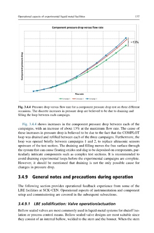
Fig. 3.4.4 Pressure drop versus flow rate for a component pressure drop test on three different
occasions. The discrete increases in pressure drop are believed to be due to draining and
filling the loop between each campaign.
Fig. 3.4.4 shows increases in the component pressure drop between each of the
campaigns, with an increase of about 13% at the maximum flow rate. The cause of
these increases in pressure drop is believed to be due to the fact that the COMPLOT
loop was drained and refilled between each of the three campaigns. Furthermore, the
loop was opened briefly between campaigns 1 and 2, to replace ultrasonic sensors
upstream of the test section. The draining and filling moves the free surface through
the system that can cause floating oxides and slag to be deposited on components, par-
ticularly intricate components such as complex test sections. It is recommended to
avoid draining experimental loops before the experimental campaigns are complete.
However, it should be mentioned that draining is not the only possible cause for
changes in pressure drop.
3.4.9 General notes and precautions during operation
The following section provides operational feedback experience from some of the
LBE facilities at SCK CEN. Operational aspects of instrumentation and component
l
setup and commissioning are covered in the subsequent subsections.
3.4.9.1 LBE solidification: Valve operation/actuation
Bellow sealed valves are most commonly used in liquid-metal systems for shutoff iso-
lation or process control means. Bellow sealed valve designs are most suitable since
they consist of an internal bellow, welded to the stem and the bonnet. When the stem