
Page 162 - Thermal Hydraulics Aspects of Liquid Metal Cooled Nuclear Reactors
P. 162
134 Thermal Hydraulics Aspects of Liquid Metal Cooled Nuclear Reactors
3.4.6 Pump startup and shutdown
Pump transient conditions such as start-up and shutdown are important in any fluid
system. The fundamentals of pump operation in a liquid-metal facility should not
be very different from any conventional fluid pumping system. General pump oper-
ational practices should be followed, such as priming the pump before use, observing
net positive suction head (NPSH) requirements and minimum pump speed/flow, and
ensuring that the pump never operates without liquid in it.
Pump start-up and shutdown procedures will depend on numerous factors such as
the system layout, the pump specific speed, and the resulting power and pressure head
during the transitions. If required by design, pumps should generally be started in a
manner such that the required starting torque or power is as low as possible. This
is particularly important for HLM such as LBE, since the power drawn by a pump
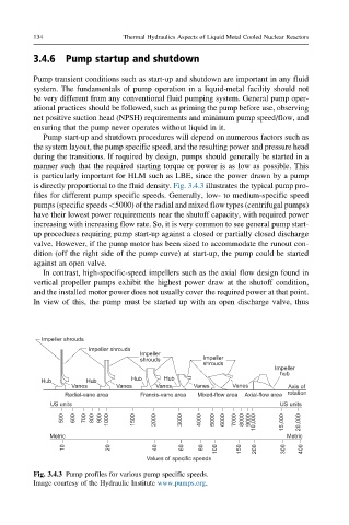
is directly proportional to the fluid density. Fig. 3.4.3 illustrates the typical pump pro-
files for different pump specific speeds. Generally, low- to medium-specific speed
pumps (specific speeds <5000) of the radial and mixed flow types (centrifugal pumps)
have their lowest power requirements near the shutoff capacity, with required power
increasing with increasing flow rate. So, it is very common to see general pump start-
up procedures requiring pump start-up against a closed or partially closed discharge
valve. However, if the pump motor has been sized to accommodate the runout con-
dition (off the right side of the pump curve) at start-up, the pump could be started
against an open valve.
In contrast, high-specific-speed impellers such as the axial flow design found in
vertical propeller pumps exhibit the highest power draw at the shutoff condition,
and the installed motor power does not usually cover the required power at that point.
In view of this, the pump must be started up with an open discharge valve, thus
Impeller shrouds
Impeller shrouds
Impeller
shrouds Impeller
shrouds
Impeller
hub
Hub Hub Hub Hub
Vanes Vanes Vanes Vanes Vanes Axis of
Radial-vane area Francis-vane area Mixed-flow area Axial-flow area rotation
US units US units
500 600 700 800 900 1000 1500 2000 3000 4000 5000 6000 7000 8000 9000 10,000 15,000 20,000
Metric Metric
10 20 40 60 80 100 150 200 300 400
Values of specific speeds
Fig. 3.4.3 Pump profiles for various pump specific speeds.
Image courtesy of the Hydraulic Institute www.pumps.org.