
Page 161 - Thermal Hydraulics Aspects of Liquid Metal Cooled Nuclear Reactors
P. 161
Operational aspects of experimental liquid metal facilities 133
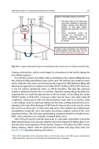
Optional: dedicated draining connection:
• The drain valve in the drain pipe
must seal completely to avoid gas
bubbles entering when filling the
system. A dual pipe system
Argon presents the possibility for this to
pressure occur
• Valve orientation could be
important for accumulation of
“debris,” depending on valve
internal geometry (applicable to
all valves)
Floating oxide precipitates and impurities
remain floating in the drain tank (*except
the impurities contained in the dip-pipe)
Fig. 3.4.2 Typical drain tank design for installation at the lowest point of a liquid-metal facility.
floating oxides/debris, which would simply be reintroduced to the facility during the
next filling sequence. 1
To avoid the scenario of possible oxide accumulation in the common filling/draining
line, dedicated filling and draining lines can be used. The draining line should of course
not be a dip tube, but a more conventional nozzle connection. This dedicated filling and
draining line approach was implemented in the CRAFT facility at SCK-CEN. However,
it was not without operational issues, as will be described. The dual line approach
requires a dedicated shutoff valve on each line. Therefore, during filling, the drain tank
is pressurized to a relatively high pressure to fill the facility via the filling line. In the
CRAFT facility at SCK-CEN, it became evident that the drain valve didn’t shut off
completely, causing gas to leak from the pressurized drain tank to the facility. Such
a valve leakage causes an argon gas leakage into the loop, resulting in gas pockets accu-
mulating in the loop. Slow drainage of LBE from the loop can also result, but this can be
the case for any drain valve. A drain valve leak such as this could be due to debris/oxide
accumulation around the valve seat region, preventing complete sealing of the valve
plug/seat interface. The valve type and mounting orientation should be considered care-
fully, with a preference for vertically orientated drain valves.
After filling the facility from the drain tank, it is advisable (if possible) to keep the
drain tank pressurized at a pressure slightly below that required for filling, that is, less
than the static head required to fill the facility. Doing so will reduce the LBE velocity
during draining, which could be significant for systems with large static head (see
Section 3.4.8 regarding draining procedures).
1
This will be dependent on the operational history of the facility, that is, the LBE oxygen concentration,
LBE temperature, and the level of mixing and entrainment prior to draining.