
Page 164 - Thermal Hydraulics Aspects of Liquid Metal Cooled Nuclear Reactors
P. 164
136 Thermal Hydraulics Aspects of Liquid Metal Cooled Nuclear Reactors
During the draining sequence, the gas in the drain tank will be pressurized, which can
be vented or fed back to the top of the facility to equalize the pressure. Drain piping
sizes and drain tank vent tubing sizes will affect the time for the facility to drain, so
these should be considered if specific drain target times are required.
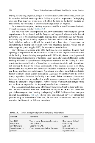
An automated/emergency draining sequence could be initiated by several criteria.
Typical criteria are listed in Table 3.4.2.
The choice of valve failure position should be determined considering the type of
experiments to be performed and the frequency of expected failures, that is, loss of
power and loss of pressurized air supply. For long-term experiments that may be jeop-
ardized by any sudden draining sequences, fail-close valves could be more suitable.
Such fail-close valves could still be actuated at a later stage if necessary, by
implementing a backup air receiver supply for pneumatic actuated valves and an
uninterruptible power supply (UPS) for solenoid actuated valves.
Early Russian experience with LBE facilities suggests avoiding draining (and
opening) of experimental LBE facilities to avoid oxide and impurity contamination
of the facility. Never draining an experimental LBE facility is not entirely practical
for most research institutions or facilities. In any case, allowing solidification inside
the loop will result in crystallization of impurities on the walls of the facility. It is pref-
erable that the crystallization of impurities occurs inside the drain tank. In addition,
not opening the facility to replace components or test sections is also most likely
unavoidable, and so, procedures should be established to minimize the ingress of oxy-
gen during shutdown and maintenance. Operational procedures should dictate that the
facility is always under an inert atmosphere (argon gas preferably) when the loop is
empty, regardless of whether the facility is hot or cold. When components, instrumen-
tation, or test sections are replaced, a slight argon overpressure in the facility will
reduce the amount of oxygen ingress. Foresee valves or install blind flanges where
test sections are expected to be frequently manipulated or removed.
The consequences of draining an LBE facility are more difficult to keep under con-
trol. Recent experience from the COMPLOT facility at SCK CEN has shown the
l
potential consequence that draining (and opening) an LBE facility can have on exper-
imental measurements. Fig. 3.4.4 shows three experimental curves of differential
pressure drop as a function of flow rate, for the same component (a mock-up fuel
assembly in this case), on different occasions.
Table 3.4.2 Typical examples of possible emergency drain criteria
Criteria Detection Cause
Low LBE Two or more thermocouples below Heat tracing failure/
temperature TAL (150°C) overcooling
Low LBE level Upper level LAL LBE leak
Loss of cover gas Cover gas pressure below threshold Depressurization of
pressure expansion tank