
Page 206 - Thermal Hydraulics Aspects of Liquid Metal Cooled Nuclear Reactors
P. 206
System thermal hydraulics for liquid metals 177
Exp 206
Exp 306
RELAP5 206
RELAP5 306
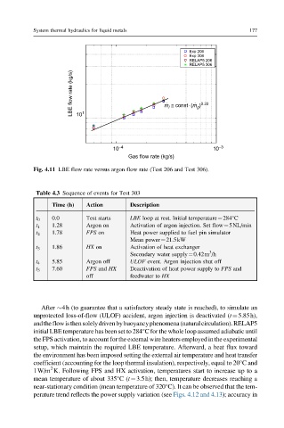
LBE flow rate (kg/s) 10 1 m @ const×(m ) 0.33
l
g
10 –4 10 –3
Gas flow rate (kg/s)
Fig. 4.11 LBE flow rate versus argon flow rate (Test 206 and Test 306).
Table 4.3 Sequence of events for Test 303
Time (h) Action Description
t 0 0.0 Test starts LBE loop at rest. Initial temperature¼284°C
t 1 1.28 Argon on Activation of argon injection. Set flow¼5NL/min
t 2 1.78 FPS on Heat power supplied to fuel pin simulator
Mean power¼21.5kW
t 3 1.86 HX on Activation of heat exchanger
3
Secondary water supply¼0.42m /h
t 4 5.85 Argon off ULOF event. Argon injection shut off
t 5 7.60 FPS and HX Deactivation of heat power supply to FPS and
off feedwater to HX
After 4h (to guarantee that a satisfactory steady state is reached), to simulate an
unprotected loss-of-flow (ULOF) accident, argon injection is deactivated (t¼5.85h),
andtheflowisthensolelydrivenbybuoyancyphenomena(naturalcirculation).RELAP5
initial LBE temperature has been set to 284°C for the whole loop assumed adiabatic until
the FPS activation, to account for the external wire heaters employed in the experimental
setup, which maintain the required LBE temperature. Afterward, a heat flux toward
the environment has been imposed setting the external air temperature and heat transfer
coefficient (accounting for the loop thermal insulation), respectively, equal to 20°Cand
2
1W/m K. Following FPS and HX activation, temperatures start to increase up to a
mean temperature of about 335°C(t¼3.5h); then, temperature decreases reaching a
near-stationary condition (mean temperature of 320°C). It can be observed that the tem-
perature trend reflects the power supply variation (see Figs. 4.12 and 4.13); accuracy in