
Page 237 - Thermal Hydraulics Aspects of Liquid Metal Cooled Nuclear Reactors
P. 237
208 Thermal Hydraulics Aspects of Liquid Metal Cooled Nuclear Reactors
5.2.3 Examples
In the frame of the European Preliminary Design Studies of an eXperimental
Accelerator-Driven System (PDS-XADS) project (Carluec et al., 2002), LBE-cooled
reactor cores were proposed. As an example, subchannel analysis was carried out, to
clarify the objectives and the functionality of SCTH programs. For this purpose, the
SCTH code MATRA was applied, which was originally developed and issued by
Korea Atomic Energy Research Institute and extended to applications of
LM-cooled reactors (Cheng, 2006).
The LBE-cooled reactor core selected in this chapter has 45 fuel assemblies with a
total thermal power of 51MW. In each fuel assembly, there are 91 fuel rods with
6.55mm diameter and 8.55mm pitch. The fuel assembly has a typical hexagonal struc-
ture. The coolant entering the fuel assemblies has a temperature of 300°C and exits the
reactor core with an average temperature 500°C. The closure models applied in the
MATRA simulation are summarized in Table 5.3.
Fig. 5.15 indicates the division of one fuel assembly into subchannels and the num-
bering system for subchannels and fuel pins. Totally, there are 186 subchannels and
are consistent with Eq. (5.2).
The coolant temperatures in all 186 subchannels at the upper end of the active
height are presented in Fig. 5.16. In each fuel assembly, several coolant temper-
ature peaks are recognized. The maximum coolant temperature is as high as 520°
C. The ratio of the temperature rise in the hot subchannel to the bundle average
value is 1.1.
Fig. 5.17 indicates the temperatures on the cladding inner surface and on the clad-
ding outer surface for all 91 fuel pins. Five temperature peaks are observed in fuel pins
FP-6, FP-17, FP-33, FP-56, and FP-85. The maximum outer cladding temperature is as
high as 550°C. Therefore, attention needs to be paid to the corrosion behavior of the
cladding materials.
Fig. 5.18 shows the maximum fuel temperature of all 91 fuel pins. It is found
that the fuel temperature peaks occur in the same fuel pins as the cladding temper-
ature peaks and is as high as 2100°C. Obviously, the safety margin to the melting
temperature of oxide fuel (about 2400°Cfor PuO 2 ) is low. Safety analysis should
be carried out for various transients, to check the safety feature of the reactor core
considered.
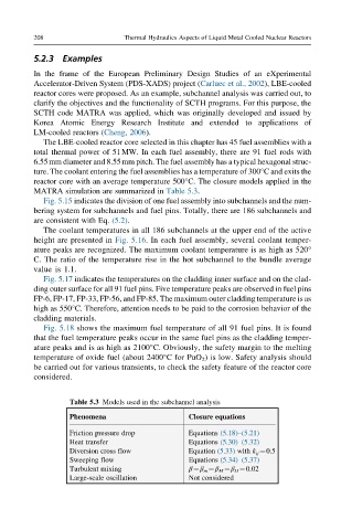
Table 5.3 Models used in the subchannel analysis
Phenomena Closure equations
Friction pressure drop Equations (5.18)–(5.21)
Heat transfer Equations (5.30)–(5.32)
Diversion cross flow Equation (5.33) with k ij ¼0.5
Sweeping flow Equations (5.34)–(5.37)
Turbulent mixing β¼β m ¼β M ¼β H ¼0.02
Large-scale oscillation Not considered