
Page 263 - Thermal Hydraulics Aspects of Liquid Metal Cooled Nuclear Reactors
P. 263
Direct numerical simulations for liquid metal applications 233
25 3
F
NF
20 2.5
2
<U> mean 10 q mean 1.5
15
1
5
0.5
0 0
0.1 1 10 100 1000 0.1 1 10 100 1000
y + y +
Fig. 6.1.1.2 Mean velocity and temperature profiles at Re τ ¼ 180 (shortest profile), 395, 590
(longest), Pr ¼ 0.01. F, NF, fluctuating and nonfluctuating thermal boundary condition,
respectively.
0.06
0.25
F 0.05
NF
0.2
0.04
0.15 q RMS 0.03
q RMS F-normal domain
F-large domain
0.1 F-very large domain
0.02 N-normal domain
N-large domain .036
0.05 0.01
0.033
50 100
0 0
0.1 1 10 100 1000 0.1 1 10 100
y + y +
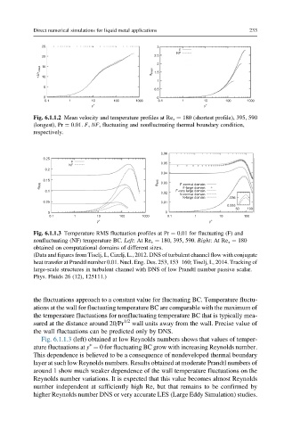
Fig. 6.1.1.3 Temperature RMS fluctuation profiles at Pr ¼ 0.01 for fluctuating (F) and
nonfluctuating (NF) temperature BC. Left:AtRe τ ¼ 180, 395, 590. Right:AtRe τ ¼ 180
obtained on computational domains of different sizes.
(Data and figures from Tiselj, I., Cizelj, L., 2012. DNS of turbulent channel flow with conjugate
heat transfer at Prandtl number 0.01. Nucl. Eng. Des. 253, 153–160; Tiselj, I., 2014. Tracking of
large-scale structures in turbulent channel with DNS of low Prandtl number passive scalar.
Phys. Fluids 26 (12), 125111.)
the fluctuations approach to a constant value for fluctuating BC. Temperature fluctu-
ations at the wall for fluctuating temperature BC are comparable with the maximum of
the temperature fluctuations for nonfluctuating temperature BC that is typically mea-
sured at the distance around 20/Pr 1/2 wall units away from the wall. Precise value of
the wall fluctuations can be predicted only by DNS.
Fig. 6.1.1.3 (left) obtained at low Reynolds numbers shows that values of temper-
+
ature fluctuations at y ¼ 0 for fluctuating BC grow with increasing Reynolds number.
This dependence is believed to be a consequence of nondeveloped thermal boundary
layer at such low Reynolds numbers. Results obtained at moderate Prandtl numbers of
around 1 show much weaker dependence of the wall temperature fluctuations on the
Reynolds number variations. It is expected that this value becomes almost Reynolds
number independent at sufficiently high Re, but that remains to be confirmed by
higher Reynolds number DNS or very accurate LES (Large Eddy Simulation) studies.