
Page 366 - Thermal Hydraulics Aspects of Liquid Metal Cooled Nuclear Reactors
P. 366
330 Thermal Hydraulics Aspects of Liquid Metal Cooled Nuclear Reactors
study allowed to correctly locate the instrumentation in order to fully capture the
blockage phenomena and the temperature maxima. On the other side, experimental
results will allow to validate CFD model and then reapply them to the larger scale
to a real reactor fuel assembly. Naveen Raj and Velusamy (2017) performed a similar
study for wire-wrapped fuel assemblies. They observe large reverse-flow zones and
conclude that detection of relatively small blockages occupying only one or a few sub-
channels through temperature measurements at the outlet will be almost impossible.
Naveen et al. (2016) analyze the impact of porous blockages in a sodium-cooled
fuel assembly. They conclude that the temperature nonuniformity caused by the wake
behind the blockage persists even up to three helical pitch lengths but still global bulk
sodium temperature monitoring at the outlet is not likely to detect slowly growing
blockages. Furthermore, they conclude that the peak cladding temperature is strongly
dependent on the assumed porosity of the blockage. Finally, they observe that rods
partially exposed to the porous blockage show large circumferential temperature
variations resulting in high thermal stress in the rods.
6.2.3.4.2 Blockages due to lost objects or migrating parts
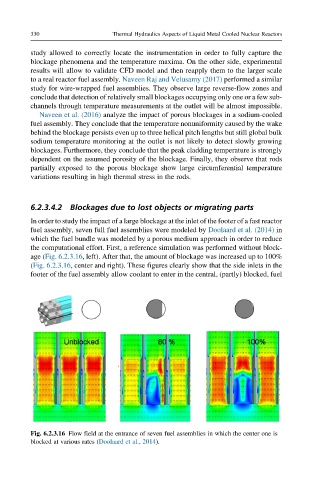
In order to study the impact of a large blockage at the inlet of the footer of a fast reactor
fuel assembly, seven full fuel assemblies were modeled by Doolaard et al. (2014) in
which the fuel bundle was modeled by a porous medium approach in order to reduce
the computational effort. First, a reference simulation was performed without block-
age (Fig. 6.2.3.16, left). After that, the amount of blockage was increased up to 100%
(Fig. 6.2.3.16, center and right). These figures clearly show that the side inlets in the
footer of the fuel assembly allow coolant to enter in the central, (partly) blocked, fuel
Fig. 6.2.3.16 Flow field at the entrance of seven fuel assemblies in which the center one is
blocked at various rates (Doolaard et al., 2014).