
Page 400 - Thermal Hydraulics Aspects of Liquid Metal Cooled Nuclear Reactors
P. 400
Multi-scale simulations of liquid metal systems 363
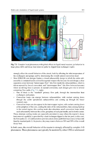
Fig. 7.1 Complex local phenomena with global effects in liquid-metal reactors: jet behavior in
large plena (left) and decay heat removal paths by dipped heat exchanger (right).
strongly affect the overall behavior of the circuit, both by affecting the inlet temperature of
the exchangers and pumps and by determining the overall natural-convection head.
l Most SFR/LFR core designs feature a closed subassembly design in which the entire sub-
assembly is contained inside a closed hexagonal wrapper (the hexcan). In such design, a clear
separation exists between “intrawrapper flow” (the flow inside the subassemblies), which is
driven upward by forced convection, and “interwrapper flow” (the flow between hexcans)
where no driving force is present. In natural convection, such designs give rise to several
competing flow paths (Fig. 7.1, right):
One of these is the “standard” primary flow path, through the intermediate heat
exchangers and pumps.
Convection loops can emerge between subassemblies, with coolant coming down
through the cooler (peripheral) subassemblies and coming up through the hotter
(central) ones.
Convection loops can also appear in the interwrapper region, with coolant coming down
at the periphery of the core, cooling the sides of the subassemblies, then coming back up
in the central region; this cooling mode also stimulates small convection loops inside
each subassembly between the cooler, periphery of each pin bundle, and its hotter center.
These alternate cooling modes are especially prevalent in cases where the reactor’s decay
heat removal capability is provided by a heat exchanger dipped in the hot pool; in this case,
the flow paths (2)–(3) outlined above provide a more direct path from heat source to heat sink
than the standard path (1). In practice, they may remove between 30% and 50% of the overall
decay heat.
In both cases, the overall behavior of the reactor is strongly affected by complex 3-D
phenomena. These phenomena can typically be modeled by either CFD or subchannel