Page 162 - Bird R.B. Transport phenomena
P. 162

146  Chapter 4  Velocity Distributions with  More Than One Independent Variable

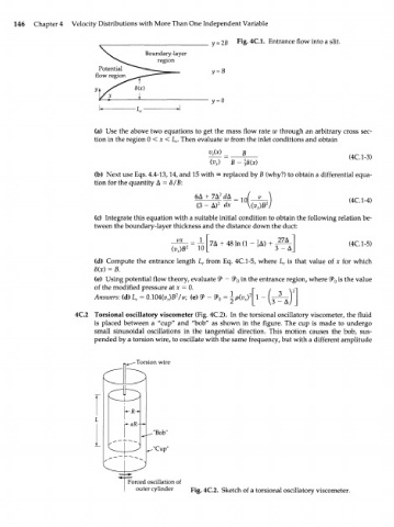
                                                           = 2B  Fig- 4C.1.  Entrance flow into a slit.


                           (a)  Use the above  two  equations  to get  the mass  flow  rate w  through  an  arbitrary  cross  sec-
                           tion in the region  0 < x <  L . Then evaluate  zv from  the inlet conditions and obtain
                                                e
                                                         v c (x)  _  В                         (4C.1-3)
                                                         <v x )  В  -  1
                           (b)  Next use  Eqs. 4.4-13,14, and  15 with  °°  replaced  by  В (why?)  to obtain a differential  equa-
                           tion for  the quantity  A = 8/B:
                                                     6Д  + 7Л 2  dA  =  1Q (  v                (4C.1-4)
                                                      (3  -  Д) 2  dx  \(v )B 2
                                                                      x
                           (c)  Integrate this equation with  a suitable  initial condition to obtain the following  relation be-
                           tween  the boundary-layer  thickness and the distance down  the duct:

                                                              48  In  (1  -  U                 (4C.1-5)
                                               (v )B 2
                                                x
                           (d)  Compute  the  entrance  length  L  from  Eq.  4C.1-5, where  L  is  that  value  of  x  for  which
                                                        e
                                                                             c
                          8(x) = B.
                           (e)  Using potential flow  theory, evaluate  9* -  <3>  in the entrance region, where  2P is the  value
                                                                                             0
                                                                   0
                           of  the modified  pressure  at x  = 0.   г
                                                 2
                                                                       2
                          Answers: (d) L  = O.W4(v )B /i>;  (e) <3>  -  %  = \p(v ) \  1 -  L
                                      c        x                      x
                                                               2     |   \3  - ,
                     4C.2  Torsional oscillatory viscometer  (Fig. 4C.2).  In the torsional  oscillatory  viscometer,  the  fluid
                           is  placed  between  a  "cup"  and  "bob"  as  shown  in  the  figure.  The  cup  is  made  to  undergo
                           small  sinusoidal  oscillations  in  the  tangential  direction.  This  motion  causes  the  bob,  sus-
                           pended by  a torsion wire, to oscillate  with  the same frequency,  but with a different  amplitude
                                      Torsion wire


                                         -"Bob"
                                         -"Cup"


                                    Forced oscillation  of
                                      outer cylinder  F  i .  4 C > 2  .  Sketch  of a torsional oscillatory  viscometer.
                                                      g
   157   158   159   160   161   162   163   164   165   166   167