
Page 212 - Bird R.B. Transport phenomena
P. 212
196 Chapter 6 Interphase Transport in Isothermal Systems
radius of the cylinder. For the creeping flow region, it has body and bottom and the form drag of the radial baffles,
been found empirically that the dependence of/on R/R cy{ respectively:
may be described by the Ladenburg-Faxen correction? so that
( \ S R(dv /dn) dS + | A Rp dA ) ' (6C.3-2)
e
5urf
surf
1 + 2 . 1 ^ - 1 (6C.2-2) Here T is the torque required to turn the impeller, S is the
z
Wall effects for falling droplets have also been studied. 6 total surface area of the tank, A is the surface area of the
(b) Design an experiment to check the graph for spheres baffles, (considered positive on the "upstream" side and
in Fig. 6.3-1. Select sphere sizes, cylinder dimensions, and negative on the "downstream side"), R is the radial dis-
appropriate materials for the experiment. tance to any surface element dS or dA from the impeller
axis of rotation, and n is the distance measured normally
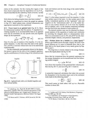
6C.3 Power input to an agitated tank (Fig. 6C.3). Show into the fluid from any element of tank surface dS.
by dimensional analysis that the power, P, imparted by a The desired solution may now be obtained by dimen-
rotating impeller to an incompressible fluid in an agitated sional analysis of the equations of motion and continuity
tank may be correlated, for any specific tank and impeller by rewriting the integrals above in dimensionless form.
shape, by the expression Here it is convenient to use D, DN, and pN^D for the char-
2
D N
P J ' P DN 2 -,Nt (6C.3-1) acteristic length, velocity, and pressure, respectively.
N D 5
3
7 8
P 6D.1 Friction factor for a bubble in a clean liquid. '
Here N is the rate of rotation of the impeller, D is the im- When a gas bubble moves through a liquid, the bulk of the
peller diameter, t is the time since the start of the opera- liquid behaves as if it were in potential flow; that is, the
tion, and Ф is a function whose form has to be determined flow field in the liquid phase is very nearly given by Eqs.
experimentally. 4B.5-2 and 3.
For the commonly used geometry shown in the figure, The drag force is closely related to the energy dissipa-
the power is given by the sum of two integrals represent- tion in the liquid phase (see Eq. 4.2-18)
ing the contributions of friction drag of the cylindrical tank
(6D.1-1)
F k v x = E v
Show that for irrotational flow the general expression for
Impeller Baffle the energy dissipation can be transformed into the follow-
ing surface integral:
2
E = /x/(n • Vv ) dS (6D.1-2)
v
Next show that insertion of the potential flow velocity pro-
files into Eq. 6D.1-2, and use of Eq. 6D.1-1 leads to
48
t — (6D.1-3)
Re
A somewhat improved calculation that takes into account
the dissipation in the boundary layer and in the turbulent
9
Top view Side view wake leads to the following result:
f= — (\ 1 2 (6D.1-4)
Fig. 6C.3. Agitated tank with a six-bladed impeller and 1 Re\ VRe"
four vertical baffles. This result seems to hold rather well up to a Reynolds
number of about 200.
5
R. Ladenburg, Ann. Physik (4), 23, 447 (1907); H. Faxen,
dissertation, Uppsala (1921). For extensive discussions of wall
effects for falling spheres, see J. Happel and H. Brenner, Low 7 L. Landau and E. M. Lifshitz, Fluid Mechanics, Pergamon,
Reynolds Number Hydrodynamics, Martinus Nijhoff, The Hague Oxford (1987), pp. 182-183.
(1983). 8 G. K. Batchelor, An Introduction to Fluid Dynamics,
J. R. Strom and R. C. Kintner, AIChE Journal 4,153-156 Cambridge University Press, (1967), pp. 367-370.
ь
(1958). 9 D. W. Moore, /. Fluid Mech., 16,161-176 (1963).