
Page 213 - Bird R.B. Transport phenomena
P. 213
Chapter 7
Macroscopic Balances for
Isothermal Flow Systems
§7.1 The macroscopic mass balance
§7.2 The macroscopic momentum balance
§7.3 The macroscopic angular momentum balance
§7.4 The macroscopic mechanical energy balance
§7.5 Estimation of the viscous loss
§7.6 Use of the macroscopic balances for steady-state problems
§7.7° Use of the macroscopic balances for unsteady-state problems
§7.8* Derivation of the macroscopic mechanical energy balance
In the first four sections of Chapter 3 the equations of change for isothermal systems were
presented. These equations were obtained by writing conservation laws over a "micro-
scopic system"—namely, a small element of volume through which the fluid is flowing. In
this way partial differential equations were obtained for the changes in mass, momentum,
angular momentum, and mechanical energy in the system. The microscopic system has no
solid bounding surfaces, and the interactions of the fluid with solid surfaces in specific
flow systems are accounted for by boundary conditions on the differential equations.
In this chapter we write similar conservation laws for "macroscopic systems"—that
is, large pieces of equipment or parts thereof. A sample macroscopic system is shown in
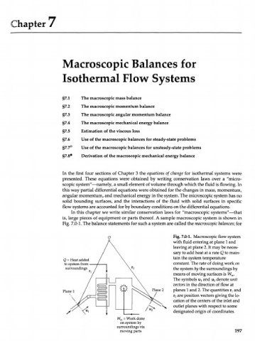
Fig. 7.0-1. The balance statements for such a system are called the macroscopic balances; for
Fig. 7.0-1. Macroscopic flow system
with fluid entering at plane 1 and
leaving at plane 2. It may be neces-
sary to add heat at a rate Q to main-
tain the system temperature
Q = Heat added
to system from constant. The rate of doing work on
surroundings the system by the surroundings by
means of moving surfaces is W .
m
The symbols щ and u denote unit
2
vectors in the direction of flow at
Plane 1 Plane 2 planes 1 and 2. The quantities r and
T
r are position vectors giving the lo-
2
\ cation of the centers of the inlet and
outlet planes with respect to some
designated origin of coordinates.
W = Work done
m
on system by
surroundings via
moving parts 197