
Page 217 - Bird R.B. Transport phenomena
P. 217
§7.2 The Macroscopic Momentum Balance 201
If the total amount of momentum in the system does not change with time, then we get
the steady-state macroscopic momentum balance
m tot g (7.2-3)
(v)
Once again we emphasize that this is a vector equation. It is useful for computing the force
of the fluid on the solid surfaces, F^ , such as the force on a pipe bend or a turbine blade.
s
Actually we have already used a simplified version of the above equation in Eq. 6.1-3.
Notes regarding turbulent flow: (i) For turbulent flow it is_customary to replace (v) by
2
2
2
(v) and (v ) by (v ); in the latter we are neglecting the term (v' ), which is generally small
2
2
with respect to (v ). (ii) Then we further replace (v )/(v) by (v). The error in doing this is
quite small; for the empirical \ power law velocity profile given in Eq. 5.1-4, (v )/{v) =
2
%{v), so that the error is about 2%. (iii) When we make this assumption we will normally
drop the angular brackets and overbars to simplify the notation. That is, we will let
(щ) = v and (v ) = v , with similar simplifications for quantities at plane 2.
2
2
A
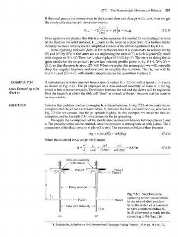
EXAMPLE 7.2-1 A turbulent jet of water emerges from a tube of radius R } = 2.5 cm with a speed v x = 6 m/s,
as shown in Fig. 7.2-1. The jet impinges on a disk-and-rod assembly of mass m = 5.5 kg,
Force Exerted by a Jet which is free to move vertically. The friction between the rod and the sleeve will be neglected.
(Part a) Find the height h at which the disk will "float' 7 as a result of the jet. Assume that the water is
1
incompressible.
SOLUTION To solve this problem one has to imagine how the jet behaves. In Fig. 7.2-1 (a) we make the as-
sumption that the jet has a constant radius, R v between the tube exit and the disk, whereas in
Fig. 7.2-1 (b) we assume that the jet spreads slightly. In this example, we make the first as-
sumption, and in Example 7.4-1 we account for the jet spreading.
We apply the z-component of the steady-state momentum balance between planes 1 and
2. The pressure terms can be omitted, since the pressure is atmospheric at both planes. The z
component of the fluid velocity at plane 2 is zero. The momentum balance then becomes
mg = ' - (irR h)pg (7.2-4)
2
When this is solved for h, we get (in SI units)
m (6) 2 5.5 0.87 m (7.2-5)
2
8 pirR , (9.807) 77(0.025) : =
Disk-rod assembly
I t / w i t h m a s s '« \ ]||[
Plane3
^ r ^ " P l a n e 2 Plane2
- Rising water jet -
Fig. 7.2-1. Sketches corre-
sponding to the two solutions
Plane 1 Plane 1 to the jet-and-disk problem.
- Tube with radius R^ In (a) the water jet is assumed
Tube to have a uniform radius R].
In (b) allowance is made for the
(a) (b) spreading of the liquid jet.
1
K. Federhofer, Aufgaben aus der Hydromechanik, Springer-Verlag, Vienna (1954), pp. 36 and 172.