
Page 218 - Bird R.B. Transport phenomena
P. 218
202 Chapter 7 Macroscopic Balances for Isothermal Flow Systems
§7.3 THE M A C R O S C O P I C ANGULAR M O M E N T U M BALANCE
The development of the macroscopic angular momentum balance parallels that for the
(linear) momentum balance in the previous section. All we have to do is to replace "mo-
mentum" by "angular momentum" and "force" by "torque."
To describe the angular momentum and torque we have to select an origin of coor-
dinates with respect to which these quantities are evaluated. The origin is designated by
"O" in Fig. 7.0-1, and the locations of the midpoints of planes 1 and 2 with respect to this
origin are given by the position vectors т and r .
г
2
Once again we make assumptions (i)-(iv) introduced in §§7.1 and 7.2. With these as-
sumptions the rate of entry of angular momentum at plane 1, which is /[r x pv](v • u)dS
evaluated at that plane, becomes Pi^i^SJrj X u j , with a similar expression for the rate
at which angular momentum leaves the system at 2.
The unsteady-state macroscopic angular momentum balance may now be written as
Pl(Vb)Si[li X u j - p (^)S [r x u ]
dt "* 2 2 2 2
rate of rate of angular rate of angular
increase of momentum momentum
angular in at plane 1 out at plane 2
momentum
+ S,[r ! x u j - p S [r x u ] + T ^ + T (7.3-1)
Pl
2
s
f
2
2
2
ext
x
torque due to torque due to torque external
pressure on pressure on of solid torque
fluid at fluid at surface on fluid
plane 1 plane 2 on fluid
Here L tot = /p[r X v]dV is the total angular momentum within the system, and T =
ext
/[r X pg] dV is the torque on the fluid in the system resulting from the gravitational force.
This equation can also be written as
(7.3-2)
Finally, the steady-state macroscopic angular momentum balance is
"
T^ = А ( Ц W + pSj[r X ] + T (7.3-3)
s U ext
This gives the torque exerted by the fluid on the solid surfaces.
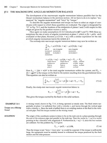
EXAMPLE 7.3-1 A mixing vessel, shown in Fig. 7.3-1, is being operated at steady state. The fluid enters tan-
gentially at plane 1 in turbulent flow with a velocity v and leaves through the vertical pipe
A
Torque on a Mixing with a velocity i?. Since the tank is baffled there is no swirling motion of the fluid in the verti-
2
Vessel cal exit pipe. Find the torque exerted on the mixing vessel.
SOLUTION The origin of the coordinate system is taken to be on the tank axis in a plane passing through
u
the axis of the entrance pipe and parallel to the tank top. Then the vector [r^ X j is a vector
pointing in the z direction with magnitude R. Furthermore [r X u ] = 0, since the two vectors
2
2
are collinear. For this problem Eq. 7.3-3 gives
T^s = (pv\S + pS^)Rb (7.3-4)
x l z
Thus the torque is just "force X lever arm," as would be expected. If the torque is sufficiently
large, the equipment must be suitably braced to withstand the torque produced by the fluid
motion and the inlet pressure.