Page 235 - Bird R.B. Transport phenomena
P. 235

§7.7  Use of the Macroscopic Balances for Unsteady-State Problems  219

      EXAMPLE   7.7-2      The liquid  in a  U-tube manometer, initially  at rest, is  set in motion by  suddenly  imposing a
                           pressure  difference  p  -  p .  Determine  the  differential  equation  for  the  motion  of  the
                                                 b
                                            a
     Manometer             manometer fluid, assuming incompressible flow and constant temperature. Obtain an expres-
     Oscillations 2        sion  for  the  tube  radius  for  which  critical  damping  occurs. Neglect  the  motion  of  the  gas
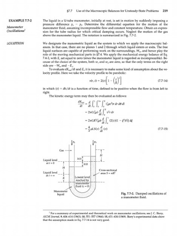
                           above the manometer liquid. The notation is summarized in Fig. 7.7-2.

     SOLUTION              We  designate  the manometric liquid  as  the system  to which  we  apply  the macroscopic bal-
                           ances. In that case, there are no planes 1 and 2 through which liquid  enters or exits. The  free
                           liquid  surfaces  are capable  of performing  work  on the surroundings, W , and hence play the
                                                                                    m
                           role  of  the moving  mechanical parts  in §7.4. We  apply  the mechanical energy  balance  of  Eq.
                           7.4-2, with E  set equal to zero (since the manometer liquid  is regarded  as incompressible). Be-
                                     c
                           cause  of the choice of the system, both w x  and w 2  are zero, so that the only terms on the right
                           side are -  W  and —E .
                                     m
                                            v
                              To evaluate dK /dt  and E  it is necessary  to make some kind  of assumption about the ve-
                                                   v
                                                                   -m
                                          tot
                           locity profile. Here we take the velocity  profile  to be parabolic:
                                                      v(r, t) = 2(v)\ 1                        (7.7-14)
                           in which (v) = dh/dt is a function  of time, defined  to be positive when the flow is from  left to
                           right.
                              The kinetic energy term may then be evaluated  as follows:

                                                      d  Г  f 27T  (  R  { i p v 2 ) r d r d e d i
                                                  •tot =
                                                  t   at  Jo  Jo  Jo
                                                      о  г/1  ч  d  f R  j
                                                    =  2ТГ1ЛГР)  —  v  2  r  dr
                                                            dt  Jo
                                                                  1
                                                            2
                                                    = 27rLR (|p)|[ |
                                                                                               (7.7-15)
                                                             dt

                                                         Рь


                                                            T
                                     Gas -
                                                             Я
                           Liquid level        hit)
                             at t = О  Г           hit)
                                      H
                                                            Cross-sectional
                           Liquid level  j_                ^  area  S  =  TTR 2
                             at  t  =  oo  |
                                       К      Lowest level
                                              reached by
                                              manometer
                                              fluid  (z = 0)
                                 Manometer
                                   liquid                                Fig. 7.7-2.  Damped oscillations of
                                                                         a manometer fluid.


                              2  For a summary of experimental and theoretical work on manometer oscillations, see J. C.  Biery,
                           AIChE Journal, 9, 606-614 (1963); 10, 551-557 (1964); 15, 631-634 (1969). Biery's experimental data show
                           that the assumption made in Eq. 7.7-14 is not very good.
   230   231   232   233   234   235   236   237   238   239   240