
Page 249 - Bird R.B. Transport phenomena
P. 249
3.1 Examples of the Behavior of Polymeric Liquids 233
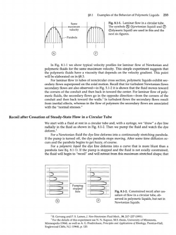
Same Fig. 8.1-1. Laminar flow in a circular tube.
- maximum - The symbols (§) (Newtonian liquid) and (£
velocity (Polymeric liquid) are used in this and the
next six figures.
-Parabola
® ©
In Fig. 8.1-1 we show typical velocity profiles for laminar flow of Newtonian and
polymeric fluids for the same maximum velocity. This simple experiment suggests that
the polymeric fluids have a viscosity that depends on the velocity gradient. This point
will be elaborated on in §8.3.
For laminar flow in tubes of noncircular cross section, polymeric liquids exhibit sec-
ondary flows superposed on the axial motion. Recall that for turbulent Newtonian flows
secondary flows are also observed—in Fig. 5.1-2 it is shown that the fluid moves toward
the corners of the conduit and then back in toward the center. For laminar flow of poly-
meric fluids, the secondary flows go in the opposite direction—from the corners of the
2
conduit and then back toward the walls. In turbulent flows the secondary flows result
from inertial effects, whereas in the flow of polymers the secondary flows are associated
with the "normal stresses."
Recoil after Cessation of Steady-State Flow in a Circular Tube
We start with a fluid at rest in a circular tube and, with a syringe, we "draw" a dye line
radially in the fluid as shown in Fig. 8.1-2. Then we pump the fluid and watch the dye
deform. 3
For a Newtonian fluid the dye line deforms into a continuously stretching parabola.
If the pump is turned off, the dye parabola stops moving. After some time diffusion oc-
curs and the parabola begins to get fuzzy, of course.
For a polymeric liquid the dye line deforms into a curve that is more blunt than a
parabola (see Eq. 8.1-1). If the pump is stopped and the fluid is not axially constrained,
the fluid will begin to "recoil" and will retreat from this maximum stretched shape; that
1
1 ^
1 ^ - i ^
Pumping
stopped i ^ i
\ _ ^
here Fig. 8.1-2. Constrained recoil after ces-
1 ^ i ^ i
sation of flow in a circular tube, ob-
served in polymeric liquids, but not in
(N) © Newtonian liquids.
2
B. Gervang and P. S. Larsen, /. Non-Newtonian Fluid Mech., 39, 217-237 (1991).
3
For the details of this experiment see N. N. Kapoor, M.S. thesis, University of Minnesota,
Minneapolis (1964), as well as A. G. Fredrickson, Principles and Applications ofRheology, Prentice-Hall,
Englewood Cliffs, N.J. (1964), p. 120.