
Page 622 - Bird R.B. Transport phenomena
P. 622
602 Chapter 19 Equations of Change for Multicomponent Systems
Refrigerant
vapor at T = T,.
Air out at L
;> Water film at T = T r
^ Liquefied refrigerant -^
atT=T r
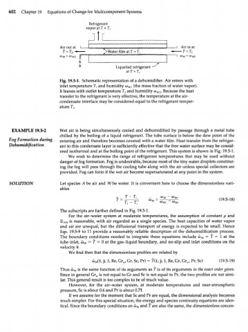
Fig. 19.5-1. Schematic representation of a dehumidifier. Air enters with
inlet temperature T and humidity o) W} (the mass fraction of water vapor).
}
It leaves with outlet temperature T and humidity w . Because the heat
2
W2
transfer to the refrigerant is very effective, the temperature at the air-
condensate interface may be considered equal to the refrigerant temper-
ature T r
EXAMPLE 19.5-2 Wet air is being simultaneously cooled and dehumidified by passage through a metal tube
chilled by the boiling of a liquid refrigerant. The tube surface is below the dew point of the
Fog Formation during entering air and therefore becomes covered with a water film. Heat transfer from the refriger-
Dehumidification ant to this condensate layer is sufficiently effective that the free water surface may be consid-
ered isothermal and at the boiling point of the refrigerant. This system is shown in Fig. 19.5-1.
We wish to determine the range of refrigerant temperatures that may be used without
danger of fog formation. Fog is undesirable, because most of the tiny water droplets constitut-
ing the fog will pass through the cooling tube along with the air unless special collectors are
provided. Fog can form if the wet air become supersaturated at any point in the system.
SOLUTION Let species Л be air and W be water. It is convenient here to choose the dimensionless vari-
ables
T-T
"T 1 r Q) Wr (19.5-18)
г, - T; (x) m
The subscripts are further defined in Fig. 19.5-1.
For the air-water system at moderate temperatures, the assumption of constant p and
4b is reasonable, with air regarded as a single species. The heat capacities of water vapor
A]N
and air are unequal, but the diffusional transport of energy is expected to be small. Hence
Eqs. 19.5-9 to 11 provide a reasonably reliable description of the dehumidification process.
The boundary conditions needed to integrate these equations include CJ = f = 1 at the
W
tube inlet, a> = f = 0 at the gas-liquid boundary, and no-slip and inlet conditions on the
w
velocity v.
We find then that the dimensionless profiles are related by
io (x, y, z, Re, Gr , Gr, Sc, Pr) = f(x, y, z, Re, Gr, Gr , Pr, Sc) (19.5-19)
w w w
Thus a) is the same function of its arguments as f is of its arguments in the exact order given.
w
Since in general Gr^ is not equal to Gr and Sc is not equal to Pr, the two profiles are not simi-
lar. This general result is too complex to be of much value.
However, for the air-water system, at moderate temperatures and near-atmospheric
pressure, Sc is about 0.6 and Pr is about 0.71.
If we assume for the moment that Sc and Pr are equal, the dimensional analysis becomes
much simpler. For this special situation, the energy and species continuity equations are iden-
tical. Since the boundary conditions onw and T are also the same, the dimensionless concen-
w