
Page 148 - Trenchless Technology Piping Installation and Inspection
P. 148
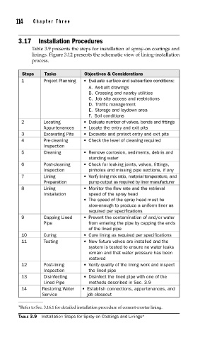
114    Cha pte r  T h ree


     3.17 Installation Procedures
          Table 3.9 presents the steps for installation of spray-on coatings and
          linings. Figure 3.12 presents the schematic view of lining-installation
          process.


      Steps    Tasks          Objectives & Considerations
      1        Project Planning  •   Evaluate surface and subsurface conditions:
                                A. As-built drawings
                                B.  Crossing and nearby utilities
                                C.  Job site access and restrictions
                                D. Traffic management
                                E.  Storage and laydown area
                                F. Soil conditions
      2        Locating       • Evaluate number of valves, bends and fittings
               Appurtenances  •  Locate the entry and exit pits
      3        Excavating Pits  •  Excavate and protect entry and exit pits
      4        Pre-cleaning   •  Check the level of cleaning required
               Inspection
      5        Cleaning       •  Remove corrosion, sediments, debris and
                                standing water
      6        Post-cleaning   • Check for leaking joints, valves, fittings,
               Inspection       pinholes and missing pipe sections, if any
      7        Lining         • Verify lining mix ratio, material temperature, and
               Preparation      pump output as required by liner manufacturer
      8        Lining         • Monitor the flow rate and the retrieval
               Installation     speed of the spray head
                              • The speed of the spray head must be
                                slow-enough to produce a uniform liner as
                                required per specifications
      9        Capping Lined   • Prevent the contamination of and/or water
               Pipe             from entering the pipe by capping the ends
                                of the lined pipe
      10       Curing         •  Cure lining as required per specifications
      11       Testing        •  New fixture valves are installed and the
                                system is tested to ensure no water leaks
                                remain and that water pressure has been
                                restored
      12       Post-lining    • Verify quality of the lining work and inspect
               Inspection       the lined pipe
      13       Disinfecting   • Disinfect the lined pipe with one of the
               Lined Pipe       methods described in Sec. 3.9
      14      Restoring Water   • Establish connections, appurtenances, and
              Service          job closeout

     ∗ Refer to Sec. 3.16.1 for detailed installation procedure of cement-mortar lining.
     TABLE 3.9  Installation Steps for Spray on Coatings and Linings ∗