
Page 253 - Trenchless Technology Piping Installation and Inspection
P. 253
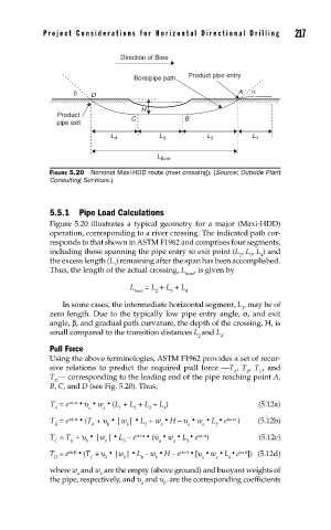
Pr oject Considerations for Horizontal Dir ectional Drilling   217


                            Direction of Bore

                               Bore/pipe path  Product pipe entry
                β   D                                    A  α

                                 H
            Product
            pipe exit         C             B
                         L  4        L 3         L 2        L 1

                                     L bore
          FIGURE 5.20  Nominal Maxi-HDD route (river crossing). (Source: Outside Plant
          Consulting Services.)


          5.5.1  Pipe Load Calculations
          Figure 5.20 illustrates a typical geometry for a major (Maxi-HDD)
          operation, corresponding to a river crossing. The indicated path cor-
          responds to that shown in ASTM F1962 and comprises four segments,
          including those spanning the pipe entry to exit point (L , L , L ) and
                                                         2  3  4
          the excess length (L ) remaining after the span has been accomplished.
                          1
          Thus, the length of the actual crossing, L  , is given by
                                            bore
                              L   = L  + L  + L
                               bore  2  3   4
             In some cases, the intermediate horizontal segment, L , may be of
                                                          3
          zero length. Due to the typically low pipe entry angle, α, and exit
          angle, β, and gradual path curvature, the depth of the crossing, H, is
          small compared to the transition distances L and L .
                                               2     4
          Pull Force
          Using the above terminologies, ASTM F1962 provides a set of recur-
          sive relations to predict the required pull force ––T , T , T , and
                                                        A  B  C
          T –– corresponding to the leading end of the pipe reaching point A,
           D
          B, C, and D (see Fig. 5.20). Thus,
               υa α
          T  = e · υ · w · (L  + L  + L  + L )                (5.12a)
           A        a  a   1   2   3  4
               υb α
          T  = e · (T  + υ · |w |· L  + w · H – υ · w · L · e υa α  )   (5.12b)
           B        A   b    b    2   b     a   a  2
                               υb α
          T  = T  + υ · |w |· L  – e · (υ · w · L · e υa α )  (5.12c)
           C   B   b    b   3        a   a  3
                                          υb α
               υb β
          T  = e · (T  + υ · |w |· L  – w · H – e · [υ · w · L · e υa α ]) (5.12d)
           D        C   b   b    4  b           a  a   4
          where w  and w  are the empty (above ground) and buoyant weights of
                 a     b
          the pipe, respectively, and υ  and υ . are the corresponding coefficients
                                 a    b