
Page 254 - Trenchless Technology Piping Installation and Inspection
P. 254
218 Cha pte r F i v e
of friction. Equation (5.12) is sufficiently general to consider the pos-
sible implementation of anti-buoyant measures to reduce the other-
wise high values of w for polyethylene pipe. In the absence of such
b
anti-buoyancy measures, or with low friction pipe supports (e.g., roll-
ers) outside the borehole, the maximum pull force will tend to occur
toward the end of the installation (e.g., T or T ).
C D
Equation (5.12) is based upon conventional Coulomb friction,
which assumes that drag forces on the pipe are proportional to the
normal bearing forces applied at the pipe surface, with the propor-
tionality constant designated as the “coefficient of friction.” Such
bearing forces may be due to the dead (empty) weight of the pipe
where above ground, the buoyant weight of the submerged pipe
(possibly mitigated by anti-buoyancy measures), bearing/bending
forces associated with pulling a stiff pipe around a curve, or bearing
forces resulting from (previously induced) axial tension tending to
pull the pipe snugly against any locally curved surfaces.
For the case of polyethylene pipe, of typically low bending
stiffness relative to that of the steel drill rods that created the grad-
ually curved original borehole path, the corresponding bearing/
bending forces may be ignored. However, the tension-induced
bearing forces are primarily dependent upon the cumulative bend
angles, which may be significant, independent of the gradual
nature or variable direction of such curves or degree of pipe bend-
ing stiffness, and are included in the analysis. Such effects com-
pounded, and in some situations may become the dominant source
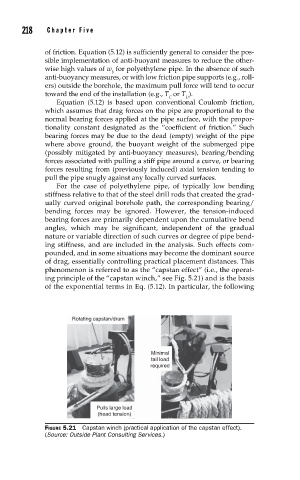
of drag, essentially controlling practical placement distances. This
phenomenon is referred to as the “capstan effect” (i.e., the operat-
ing principle of the “capstan winch,” see Fig. 5.21) and is the basis
of the exponential terms in Eq. (5.12). In particular, the following
Rotating capstan/drum
Minimal
tail load
required
Pulls large load
(head tension)
FIGURE 5.21 Capstan winch (practical application of the capstan effect).
(Source: Outside Plant Consulting Services.)